
8/10.7 dBi Dual-Band Narrow Beamwidth 3-Element MIMO Sector Antenna (J9169A) Guide v5.5.1

2 HP 8/10.7 dBi Dual-Band Narrow Beamwidth 3-Element MIMO Sector Antenna (J9169A) Guide
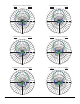
ANTENNA LOCATION
This is an outdoor antenna, but it may also be used indoors. For best re-
sults, mount the J9169A facing towards the center of the coverage area. A
line-of-sight path between the antenna and active area works best. Avoid
mounting next to a column or vertical support that could create a shadow
zone and reduce coverage.
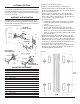
ASSEMBLY AND MOUNTING
The J9169A is shipped with a heavy duty articulating mounting kit (HP
5070-6360) that provides wide-range articulation in both the azimuth and
elevation planes. The kit allows mounting on a mast (up to 2 inches or 5.1
cm), or on a wall using wall anchors.
Assemble and mount the antenna as follows.
(See Figure 1 for wall mount and Figure 2 for pole/mast mount.)
1. Attach the antenna mount (1) to the exposed studs on the back of the
antenna using 4 SS 1/4”-20 hex nuts (10), 4 1/4”-20 SS at washers (8)
and 4 1/4”-20 SS lock washers (9)
2. Secure one side of the articulating arm (2) with 1 SS [M8] washer
external serrated (7), to the antenna mount (1) using 1 Bolt size SS
5/16”x 1-5/8”(5), 1 SS 5-16” split lock wash (4), 2 SS at washer 5-16”
(3) and 1 hex nut 5-16” (6) assemble as shown.
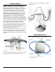
3. For mounting on a wall:
a. Using the other supplied antenna mount bracket (1) as a template
to mark holes locations, for drilling see wall diagram gure 3 for
holes size.
b. Install 4 wall expansion anchors (12).
c. Install to wall the antenna mount bracket using four SS HEX
1/4”-20 screws (13), 4 SS 1/4”-20 at washers (8), 4 1/4”-20 lock
washer (9). Or, for mounting on a pole or mast, attach the two hose
clamps (11) to antenna mount bracket (1) and encircle the pole with
each clamp and tighten.
4. Attach the pre-assembled antenna with both (1) and (2) to the other
bracket (previously mounted) using 1 SS washer external serrated (7),
using 1 Bolt size SS 5/16” 1-5/8” (5), 1 SS 5-16”split lock washer (4), 2
SS at washer 5-16” (3) and 1 hex nut (6) 5-16” assemble as shown.
Use the screw (5) to attach the free end of the articulating arm to the
mount and then secure it in place with SS hex nut (6).
5. Loosen the pivot screws (1-5/8” bolt screw (5)) as needed to position
the antenna for desired azimuth and elevation. When the antenna is
fully adjusted, tighten all hardware securely.
Item Description Qty
1 Bracket, Flange 2
2 Bracket, Linkage 1
3 5/16 Flat Washer 4
4 5/16 Lock Washer 2
5 5/16 x 1-5/8 Hex Head Bolt 2
6 5/16 Nut 2
7 Double Serrated Lock Washer 2
8 1/4 Flat Washer 8
9 1/4 Lock Washer 8
10 1/4 Nut 4
11 Clamp 2
12 Expansion Anchor 4
13 1/4 x 1-3/4 Hex Head Bolt 4
MOUNTING HARDWARE
BRACKET
ASSEMBLY
MAST MOUNT
CONFIGURATION
WALL MOUNT
CONFIGURATION
ANTENNA
INSTALLATION
Figure 1
Figure 2
Figure 3