
Datasheet: ProCurve 14 dBi Yagi Antenna


Table Of Contents
- SPECIFICATIONS
- ANTENNA LOCATION
- DESCRIPTION
- SAFETY
- MOUNTING INFORMATION
- WEEP HOLES
- 1. Vertical Mounting: When mounting vertically, find two weep holes on the broad, flat side of the radome and cover with adhesive dots.
- 2. Horizontal Mounting: When mounting horizontally, find two weep holes on the narrow edge of the radome and cover with adhesive dots. When adhesive dots are applied, check to ensure holes are fully closed.
- ASSEMBLY
- ASSEMBLY (continued)
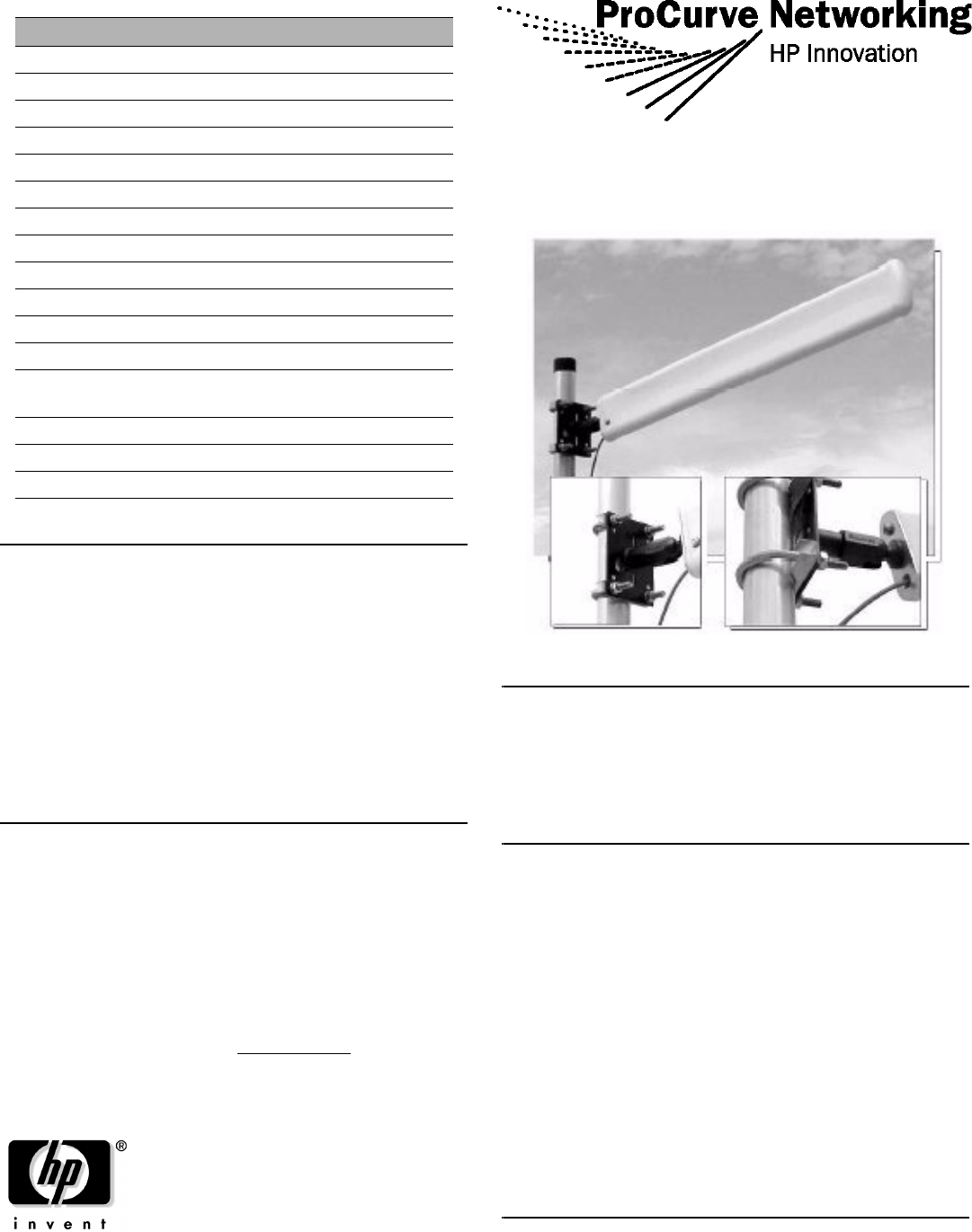
- 2. Orient for the desired ploarization and install the antenna base against the mast using the two U-bolts (04), four hex nuts (18), four lock washers (19), and two V-blocks (63) provided in the hardware kit.
- 3. If using the articulating mount, install the antenna ball into position and tilt for the desired elevation angle (Figure D). Tighten the socket screw with the supplied wrench.
- 4. Rotate the antenna to the desired directional position and tighten all hardware.
- GROUNDING
- LIGHTNING ARRESTER (optional)
- LIGHTNING ARRESTER (continued)
- J8448B Yagi-B Antenna: Radiation Plots
SPECIFICATIONS
ANTENNA LOCATION
The antenna may be mounted at interior or exterior locations. For
link installations, a line-of-sight path betwen antennas works
best. Although 2.4 GHz signals penetrate cubical dividers and
interior partitions with little attenuation, reinforced block walls,
banks of metal cabinets, or steel shelving may attenuate signals
or cause multipath, a condition where reflected signals interfere
with the primary signal. Because antenna beam width is
restricted to 15 degrees each side of center, the J8448B must be
aimed accurately during installation in order to provide optimum
gain and best performance.
HP WARRANTY INFORMATION
See the Customer Support/Warranty booklet included with this product. A copy
of the specific warranty terms applicable to your ProCurve products and replace-
ment parts can be obtained from your HP Sales and Service Office or authorized
dealer.
SUPPORT
Hewlett-Packard offers support 24 hours day, seven days a weekd through the
use of a number of automated electronic services. See the Customer Support
Warranty booklet that came with your product for information on how to use
these services to get technical support. You can also get up-to-date support
information from the ProCurve Web site: www.procurve.com
Additionally, your HP-authorized network reseller can provide you with assis-
tance, both with services that they offer and with services offered by ProCurve.
©
Copyright 2005-2006, Hewlett-Packard Company, LP
The information contained herein is subject to change
without notice.
Part Number: Part Number: 5991-4691
*5991-4691*
ProCurve 14 dBi Yagi Antenna
J8448B
DESCRIPTION
The ProCurve J8448B is a complete Kit consisting of a highly
directional 15-element Yagi enclosed in a UV stable weatherproof
radome. This antenna provides extended point-to-point link cov-
erage—or sharply focused zonal coverage—for 2.4-GHz ISM
applications.
SAFETY
The ProCurve J8448B and all associated equipment should be
installed in accordance with applicable local and national electri-
cal code guidelines to ensure safe operation.
IMPORTANT WARNING: Two pairs of weep holes are provided in
the radome: one for vertical mounting and one for horizontal
mounting. You must fill the unused pair of weep holes with
adhesive dots prior to mounting or unwanted leakage into the
radome may result. (see installation instructions)
Before connecting your external antenna to a ProCurve Wireless
Access Point, please read the instructions for using an external
antenna with the access point. These instructions explain how to
set the access point’s power levels to meet regulatory require-
ments in your area. For the latest instructions, see the Product
Manuals page for your access point, available under Technical
Support on the ProCurve Web site: www.procurve.com
Important Notice: Please read all instructions carefully before
attempting to install and use this product.
Model J8448B
Frequency, MHz 2400–2500
Gain with specified cable (dBi): 13.8 dBi
VSWR max. 1.7:1
Number Elements 15
Front-to-Back Ratio: 18 dB
E-Plane (3 dB beamwidth): 30°
H-Plane (3 dB beamwidth): 34°
Radiating Element: Brass
Impedance (Ohms) 50
Antenna Connector: Type N (female)
Weight lb. (kg) 1.25 (0.56)
Mounting Style Articulating mount
Dimensions, in.
(cm):
26-1/2 x 3-3/4 x 1-1/2
(67.3 x 9.5 x 3.8)
Enclosure UV Stable Polycarbonate
Mast Diameter, Max. in. (cm): 2-1/8 (5.4)
Cable, in (.cm) 20 (50.8) RG-303 type