
Datasheet: ProCurve 14 dBi Yagi Antenna


Table Of Contents
- SPECIFICATIONS
- ANTENNA LOCATION
- DESCRIPTION
- SAFETY
- MOUNTING INFORMATION
- WEEP HOLES
- 1. Vertical Mounting: When mounting vertically, find two weep holes on the broad, flat side of the radome and cover with adhesive dots.
- 2. Horizontal Mounting: When mounting horizontally, find two weep holes on the narrow edge of the radome and cover with adhesive dots. When adhesive dots are applied, check to ensure holes are fully closed.
- ASSEMBLY
- ASSEMBLY (continued)
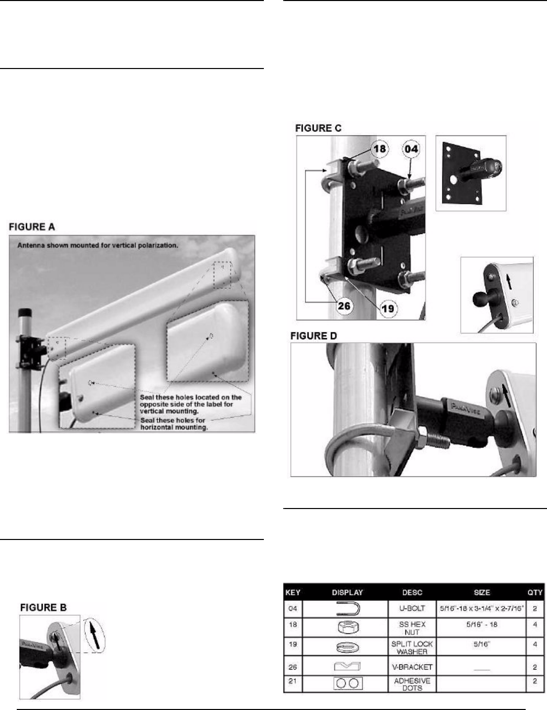
- 2. Orient for the desired ploarization and install the antenna base against the mast using the two U-bolts (04), four hex nuts (18), four lock washers (19), and two V-blocks (63) provided in the hardware kit.
- 3. If using the articulating mount, install the antenna ball into position and tilt for the desired elevation angle (Figure D). Tighten the socket screw with the supplied wrench.
- 4. Rotate the antenna to the desired directional position and tighten all hardware.
- GROUNDING
- LIGHTNING ARRESTER (optional)
- LIGHTNING ARRESTER (continued)
- J8448B Yagi-B Antenna: Radiation Plots
ProCurve Networking by HP Prod. J8448B
MOUNTING INFORMATION
The J8448B is equipped with an articulating mount, and may be
oriented for vertical or horizontal polarization. It accommodates
mast sizes up to 2-1/8 inches (4.76 cm).
WEEP HOLES
Two pairs of weep holes are provided in the radome: one for verti-
cal mounting and one for horizontal mounting. Prior to installation,
the unused pair of weep holes must be plugged with adhesive
dots to prevent leakage. Two small adhesive dots are supplied
with each antenna for this purpose. Weep-hole locations are
shown in Figure-A.
1. Vertical Mounting: When mounting vertically, find two weep holes on the broad,
flat side of the radome and cover with adhesive dots.
2. Horizontal Mounting: When mounting horizontally, find two weep holes on
the narrow edge of the radome and cover with adhesive dots.
When adhesive dots are applied, check to ensure holes are fully closed.
.
Coax Routing: During installation, avoid any sharp bend or kink in
the feed line. Also, avoid bending coax close to the radome where
it may apply pressure to the wall of the cable grommet and com-
promise the water seal. Rout coax downward–or provide a drip
loop–to ensure rainwater accumulating on the jacket flows away
from the cable grommet in the radome.
ASSEMBLY
1. Prior to mounting, find the arrow sticker on the radome. When
mounting vertically, the arrow should always point upward (Figure B).
When mounting horizontally, the arrow sticker should always be on
top of the radome.
This positioning is required (a) to
ensure weep holes fall on the bottom of
the antenna, and (b) to ensure proper
phasing when multiple antennas are
used with a harness.
ASSEMBLY (continued)
2. Orient for the desired ploarization and install the antenna base
against the mast using the two U-bolts (04), four hex nuts (18), four
lock washers (19), and two V-blocks (63) provided in the hardware kit.
3. If using the articulating mount, install the antenna ball into position
and tilt for the desired elevation angle (Figure D). Tighten the socket
screw with the supplied wrench.
4. Rotate the antenna to the desired directional position and tighten all
hardware.
GROUNDING
If mounting the antenna outdoors, system grounding and lightning
protection are essential (refer to the National Electrical Code).
Never install an antenna where it may fail and contact electrical
lines.