
ProCurve 6 dBi 5GHz Omnidirectional Antenna (J8998A) Guide 2006-05

ProCurve Networking by HP Prod. J8998A
MOUNTING
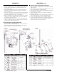
To install the antenna using the ceiling bracket:
1. Find the antenna bracket (77). Also, find two #6 phillips head screws (90) and two
#6 washers (89). Use the #6 hardware to secure the antenna bracket to the
antenna base (see Figure 1).
2. Find the tile runner bracket (HK). Remove the 1/4”-20 hex nut and flat washer
from the bracket’s carriage bolt in preparation for mounting. Discard the flat
washer-it will not be used.
3. Find the 1/4” Lock washer (16). Insert the antenna bracket onto the threaded end
of the tile-bracket bolt (Figure 1). Install the 1/4” lock washer and nut loosely, the
halves of the tile bracket must slide freely for final installation.
4. Clamp the ceiling bracket onto the support runner and tighten the 1/4” mounting
nut using a 7/16” wrench or adjustable wrench. Secure the coaxial cable along
the support runner using tape or cable ties.
5. If installing one antenna, attach the connector to the AP unit’s Primary antenna
connection. If installing a diversity system, attach the leads from the two anten-
nas to the AP unit’s Primary and Secondary jacks.
To install the antenna using the I-beam bracket:
1. For I-beam installation, first install the bracket (77) as described in Step 1 above.
Next, install I-beam clamp (80) to the bracket (see
Figure 1A) using flat washer (04), lock washer (84), and short 1/4”-20 bolt (55).
Tighten the clamp bolt to secure antenna in place on beam.
Hardware for suspended ceiling mounting
MOUNTING (cont.)
To install the antenna using the pole mount bracket:
1. Find the U-bolt (05), mast clamp (26), plus two 5/16 nuts (18) lock washers (19)
and (02) flat washers.
2. At the top of the pipe, using a 1/2 wrench or adjustable wrench, secure the U-bolt
to the clamp using the hardware provided (see Figure-2).
3. Find two more 5/16 nuts (18). Install these nuts by turning them down against the
nuts securing the U-bolt to the mast.
4. Find two antenna clamps (48), plus two 5/16 lock washers (19) and the two
remaining 5/16 nuts (18).
5. Sandwich the antenna between the two clamps at its base and slide this assem-
bly onto the U-bolt (Figure-2). Secure in place using hardware provided.
6. Secure the coaxial cable along the mast or pole using tape or cable ties.
7. If installing one antenna, attach the connector to the AP units Primary antenna
connection. If installing a diversity system, attach the leads from the two
antennas to the AP units Primary and Secondary jacks.
Hardware for pole/mast mounting