
3Com Switch 8800 Family Configuration Guide


Typical BGP Configuration Examples 387
[Switch C] interface vlan-Interface 4
[Switch C-Vlan-interface4] ip address 194.1.1.1 255.255.255.0
# Configure BGP peers and route reflector.
[Switch C] bgp 200
[Switch C-bgp] group rr internal
[Switch C-bgp] peer rr reflect-client
[Switch C-bgp] peer 193.1.1.2 group rr
[Switch C-bgp] peer 194.1.1.2 group rr
4 Configure Switch D:
# Configure VLAN 4:
[Switch D] interface vlan-interface 4
[Switch D-Vlan-interface4] ip address 194.1.1.2 255.255.255.0
# Configure BGP peers
[Switch D] bgp 200
group in internal
[Switch D-bgp] peer 194.1.1.1 group in
Using the display bgp routing-table command, you can view BGP routing table
on Switch B. Note: Switch B has known the existence of network 1.0.0.0.
Using the display bgp routing-table command ,you can view the BGP routing
table on Switch D. Note: Switch D also knows the existence of network 1.0.0.0.
Configuring BGP
Routing
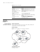
Network requirements
This example illustrates how the administrators manage the routing via BGP
attributes. All switches are configured with BGP, and IGP in AS 200 utilizes OSPF.
Switch A is in AS 100, and Switch B, Switch C and Switch D are in AS 200.Switch
A, Switch B, and Switch C operate EBGP. Switch B, Switch C and Switch D operate
IBGP.
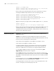
Network diagram
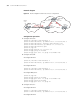
Figure 94 Networking diagram for BGP routing configuration
VLAN 4
194.1.1.2/24
VLAN 2
192.1.1.1/24
VLAN 3
193.1.1.1/24
VLAN 3
193.1.1.2/24
VLAN 5
195.1.1.2/24
VLAN 2
192.1.1.2/24
2.2.2.2
4.4.4.4
3.3.3.3
1.1.1.1
AS100
AS200
VLAN 4
194.1.1.1/24
VLAN 5
195.1.1.1/24
IBGP
IBGP
EBGP
EBGP
To network
1.0.0.0
To network
2.0.0.0
To network
4.0.0.0
To network
3.0.0.0
Switch A
Switch B
Switch C
Switch D