
H3C S7500 Series Ethernet Switches Installation Manual

Installation Manual
H3C S7500 Series Ethernet Switches Appendix B N68 Cabinet Installation
B-74
Note:
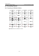
z In the figure: (1) indicates a dummy panel; (2) indicates a cabling frame; (3)
indicates a nonstandard mini panel.
z Small squares in the figure indicate guide rails. A1 through G1 and A2 through G2
are guide rails at the corresponding positions.
z M1 through M10 indicate dummy panels at the corresponding positions in the
standard configuration.
z In a DC cabinet, you may need to remove the M10 in the upper most, and move the
DC power distribution component that is originally located at the rear of the cabinet
to this position.
z In AC cabinets, no M10 exists, and the position is for the AC power distribution
component.
z The S7500 series and other devices that comply with the N68 cabinet size can be
installed in the cabinet.
z You do not need to use the cabinet exactly as the figure shows, but can adjust the
positions of guide rails and dummy panels as needed.
z Dummy panels are installed for comeliness purpose only, so you do not need to
install them when they are in shortage.
z The power of your device should be within the range allowed by the air breaker.
Refer to power distribution part for details.
z The squares with shadow marks in the figure represent the four-hole guide rails,
which can bear a weight of 90 KG; and the squares without shadow marks represent
the two-hole guide rails, which can bear a weight of 40 KG.
Table B-16 Symbol description
Symbol Description
S Indicates standard configuration (configured with one S7503 chassis)
A Configured with two S7503 chassis
B Configured with one S7506 chassis
C Configured with one S7506R chassis
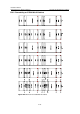
The methods of remodeling standard configuration to other configuration are as
follows:
1) Remodeling standard configuration to configuration A: Remove dummy panels M7
and M8, and remove the guide rails F1 and F2. The result of the remodeling is
configuration A.