
3COM_OS_SW8800_V3.01.32s256rc13_Release_Notes

3COM OS SW8800 V3.01.32s256rc13 Release Notes
April 25, 2013 Page 55 of 56
Configuration is saved to flash memory successfully.
Upgrading for 3C17526
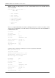
1) Miura version supports port group concept, and the QACL configuration for 3C17526 boards are
made based on port group.
[SW8800-port-group302] flow-template user-defined
[SW8800-port-group302] packet-filter inbound ip-group 3000 rule 0
[SW8800-port-group302] display this
#
port-group 302
flow-template user-defined
packet-filter inbound ip-group 3000 rule 0 system-index 1
#
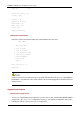
2) Before the version is upgraded to version Espada2, it is required to remove port group
configuration. After successful upgrade, it is necessary to configure the same QACL on the
corresponding primary port.
[SW8800-GigabitEthernet1/1/1] flow-template user-defined
[SW8800-GigabitEthernet1/1/1] packet-filter inbound ip-group 3000 rule 0
An 3C17526 board has four ports, whose port numbers are 0 to 3. The customized traffic flow
template and QACL can be configured only on ports 0 and 2. When the configuration is made on port
0, the configuration takes effect on both ports 0 and 1; When the configuration is made on port 2, the
configuration takes effect on both ports 2 and 3.
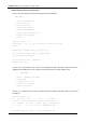
1. Some commands change with the upgrade from version Jalpa, Miura to Espada or Espada2. You
need to change the configuration file manually. For detailed information about command changes,
refer to Command Changes for Version Upgrade to Espada.
2. Before upgrading version Jalpa or Miura to Espada or Espada2, save the current configuration,
then upgrade the version and check the configuration. After the switch restarts and all boards work
normally, use the display current-configuration command to get the current configuration, and
compare with the previous configuration. For any differences, refer to Command Changes for Version
Upgrade to Espada. For any further information, please call our technical support.
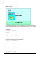
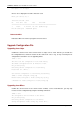
Appendix: Wire Sequence of LPU Serial Port
DB9 connector is used on PC and 2×5 double-rank receptacle is used on the LPU (Pins 1, 3, 5, 7 and
9 are in a triangle area on one side; pins 2, 4, 6, 8 and 10 are on the opposite side).
Pin 2 of DB9 connector is connected to pin 3 of 2×5 double-rank receptacle.