
3Com Switch 4200G Configuration Guide


116 CHAPTER 20: MSTP CONFIGURATION
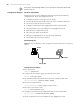
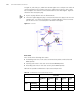
In Figure 37, switch A, B, C, and D form an MST region. Port 1 and port 2 on switch A
connect upstream to the common root. Port 5 and port 6 on switch C form a loop.
Port 3 and port 4 on switch D connect downstream to other MST regions. Figure 37
shows the roles these ports play.
■ A port can play different roles in different MSTIs.
■ The role a region edge port plays is consistent with the role it plays in the CIST. For
example, port 1 on switch A in Figure 37 is a region edge port, and it is a master
port in the CIST. So it is a master port in all MSTIs in the region.
Figure 37 Port roles
Port states
Ports can be in the following three states:
■ Forwarding state: Ports in this state can forward user packets and receive/send
BPDU packets.
■ Learning state: Ports in this state can receive/send BPDU packets.
■ Discarding state: Ports in this state can only receive BPDU packets.
Table 83 lists possible combinations of port states and port roles.
Table 83 Combinations of port states and port roles
Port role
Root/
port/Master
port
Designated
port
Region
edge
port
Alternate
port
Backup
port
Port
state
Forwarding
X X X — —
Learning
X X X — —
Discarding
X X X X X