
3Com Switch 4200G Configuration Guide


140 CHAPTER 20: MSTP CONFIGURATION
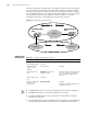
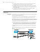
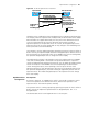
As shown in Figure 38, the upper part is the operator’s network, and the lower part is
the user network. The operator’s network comprises packet ingress/egress devices,
and the user network has networks A and B. On the operator’s network, configure
the arriving BPDU packets at the ingress to have MAC addresses in a special format,
and reconvert them back to their original formats at the egress. This is how
transparent transmission is implemented on the operator’s network.
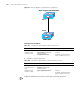
Figure 38 BPDU Tunnel network hierarchy
BPDU Tunnel
Configuration
■ The BPDU Tunnel function can only be enabled on devices with STP employed.
■ The BPDU Tunnel function can only be enabled on access ports.
■ To enable the BPDU Tunnel function, make sure the links between operator’s
networks are trunk links.
■ As the VLAN-VPN function is unavailable on ports with 802.1x, GVRP, GMRP, STP,
or NTDP employed, the BPDU Tunnel function is not applicable to these ports.
Packet ingress/egress
device
Network BNetwork A
Net wor k
Packet ingress/egress
device
Operator’ s Network
Users Network
Packet ingress/egress
device
Network BNetwork A
Net wor k
Packet ingress/egress
device
Operator’ s Network
Users Network
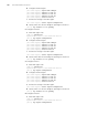
Table 117 Configure the BPDU Tunnel function
Operation Command Description
Enter system view system-view -
Enable MSTP globally stp enable -
Enable the BPDU
Tunnel function
globally
vlan-vpn tunnel Required
Enter Ethernet port
view
interface interface-type
interface-number
Make sure that you enter the Ethernet
port view of the port for which you
want to enable the BPDU Tunnel
function.
Disable MSTP for the
port
stp disable -
Enable the VLAN VPN
function for the
Ethernet port
vlan-vpn enable Required
By default, the VLAN VPN function is
disabled on all ports.