
3Com Switch 4200G Configuration Guide


IGMP Snooping Configuration Example 257
2 Enable IGMP Snooping on VLAN 10 where no Layer 3 multicast protocol is enabled.
[4200G] vlan 10
[4200G-vlan10] igmp-snooping enable
Example 2 Configure multicast VLAN on Layer 2 and Layer 3 switches.
Network requirements
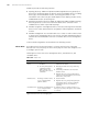
Table 230 describes the network devices involved in this example and the
configurations you should make on them.
Configure a multicast VLAN, so that the users in VLAN 2 and VLAN 3 can receive
multicast streams through the multicast VLAN.
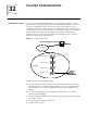
Network diagram
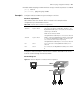
Figure 82 Network diagram for multicast VLAN configuration
Table 230 Network devices and their configurations
Device Description
Switch A Layer 3 switch The interface IP address of VLAN 20 is 168.10.1.1. The
GigabitEthernet1/0/1 port is connected to the workstation
and belongs to VLAN 20.
VLAN 10 is the multicast VLAN.
The GigabitEthernet1/0/10 port is connected to Switch B.
Switch B Layer 2 switch VLAN 2 contains the GigabitEthernet1/0/1 port and VLAN
3 contains the GigabitEthernet1/0/2 port. The two ports
are connected to PC1 and PC2 respectively.
The GigabitEthernet1/0/10 port is connected to Switch A.
PC 1 User 1 PC1 is connected to the GigabitEthernet1/0/1 port on
Switch B.
PC 2 User 2 It is connected to the GigabitEthernet1/0/2 port on Switch
B.
PC 2PC 2PC 2PC 2
PC 1PC 1PC 1PC 1
Switch A
Workstation
Switch B
PC 2PC 2PC 2PC 2
PC 1PC 1PC 1PC 1
Switch A
WorkstationWorkstation
Switch B