
3Com Switch 4200G Configuration Guide


288 CHAPTER 34: RMON CONFIGURATION
Displaying and
Debugging RMON
After the above configuration, you can execute the display command in any view to
display the RMON running status, and verify the effect of the configuration.
RMON Configuration
Example
Network requirements
■ Ensure that the SNMP agents are correctly configured before performing RMON
configuration.
■ The switch to be tested has a configuration terminal connected to its console port
and is connected to a remote NMS through Internet. Create an entry in the
Ethernet statistics table to make statistics on the Ethernet port performance for
network management.
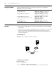
Network diagram
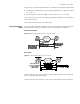
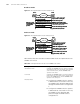
Figure 88 Network diagram for RMON configuration
Configuration procedures
1 Configure RMON.
<S4200G> system-view
[4200G] interface GigabitEthernet1/0/1
[4200G-GigabitEthernet1/0/1] rmon statistics 1 owner user1-rmon
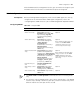
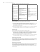
Table 255 Display and debug RMON
Operation Command
Display RMON statistics display rmon statistics [ interface-type
interface-number | unit unit-number ]
Display RMON history information display rmon history [ interface-type
interface-number | unit unit-number ]
Display RMON alarm information display rmon alarm [ entry-number ]
Display extended RMON alarm information display rmon prialarm [
prialarm-entry-number ]
Display RMON events display rmon event [ event-entry ]
Display RMON event logs display rmon eventlog [ event-entry ]
Console Port
Netw ork Port
Sw itc h
Internet
Console Port
Netw ork Port
Sw itc h
Internet