
3Com Switch 4200G Configuration Guide

300 CHAPTER 35: NTP CONFIGURATION
CAUTION:
■ The source IP address in an NTP packet is the address of the sending interface
specified by the ntp-service unicast-server command or the ntp-service
unicast-peer command if you provide the address of the sending interface in
these two commands.
■ Dynamic connections can only be established when a switch operates in passive
peer mode, NTP broadcast client mode, or NTP multicast client mode. In other
modes, the connections established are static.
Displaying and
Debugging NTP
After the above configuration, you can execute the display command in any view to
display the running status of the NTP configuration, and verify the effect of the
configuration.
Configuration
Example
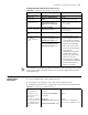
NTP Server Mode
Configuration
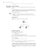
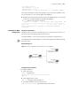
Network requirements
Configure the local clock of S4200G 1 to be NTP master clock, with the stratum being
2.
S4200G1 is a switch that allows the local clock to be the master clock.
A S4200G 1 series switch operates in client mode, with S4200G2 as the time server.
S4200G 2 operates in server mode automatically.
The 1, 2, 3, etc. destinations in the switch names are for explanation purposes only
and are not part of the command structure.
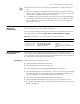
Disable the interface
from receiving NTP
packets
ntp-service in-interface disable Optional
By default, a VLAN interface
receives NTP packets.
Display the session
information maintained
by the NTP services
display ntp-service sessions [
verbose ]
This command can be executed in
any view.
Table 261 Configure optional NTP parameters (Continued)
Operation Command Description
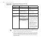
Table 262 Display and debug NTP
Operation Command
Display the status of NTP service display ntp-service status
Display the information about the sessions
maintained by NTP
display ntp-service sessions [ verbose ]
Display the brief information about the NTP
time servers of the reference clock sources that
the local device traces to
display ntp-service trace