
3Com Switch 7750 Configuration Guide Guide

108 CHAPTER 12: ISOLATE-USER-VLAN CONFIGURATION
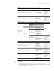
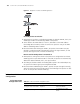
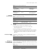
Figure 31 Diagram for isolate-user-VLAN application
Forward packets to Switch A
1 When packets sent by PC reached Ethernet1/0/4, the default VLAN ID, that is, the
VLAN tag of VLAN 3 is automatically added to the packets.
2 Switch B learns the MAC address of the PC, and adds it to the MAC address
forwarding table of VLAN 3, and at the same time copies the entry to the MAC
address forwarding table of VLAN 5.
3 Because Ethernet1/0/1 belongs to VLAN 3, the packets from VLAN 3 can pass
through it, and Ethernet1/0/1 automatically removes the tag of VLAN 3, so that
packets reaching Switch A is without the VLAN tag.
Receive and forward packets from Switch A
1 When packets coming from Switch A (the packets are configured to be without
VLAN tag) reach to port Ethernet1/0/1 of Switch B, the packets are automatically
added with default VLAN ID, that is, the tag of VLAN 5.
2 According to the MAC address forwarding table copied in the outbound process,
the system will find the egress port being Ethernet1/0/4.
3 Because Ethernet1/0/4 belongs to VLAN 5, packets can pass through it normally,
and at the same time, Ethernet1/0/4 removes the VLAN tag of the packets. So that
the PC receives packets without VLAN tag.
Isolate-User-VLAN
Configuration
Isolate-User-VLAN
Configuration Tasks
Switch B
Switch A
E1/0/1
Isolate-user 5
Switch B
Switch ASwitch A
E1/0/4
Isolate-user 5
Switch B
Switch ASwitch A
E1/0/1
Isolate-user 5
Switch B
Switch ASwitch A
E1/0/4
Isolate-user
-VLAN
5
VLAN3
Switch B
Switch ASwitch A
E1/0/1
Isolate-user 5
Switch B
Switch ASwitch A
E1/0/4
Isolate-user 5
Switch B
Switch ASwitch A
E1/0/1
Isolate-user 5
Switch B
Switch ASwitch A
E1/0/4
Isolate-user
-VLAN
5
VLAN3
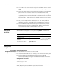
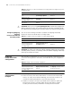
Tabl e 54 isolate-user-VLAN configuration tasks
Operation Description Related section
Configure isolate-user-VLAN Required
“Configuring
Isolate-User-VLAN”
Configure secondary VLAN Required
“Configuring Secondary
VLAN”