
3Com Switch 7750 Configuration Guide Guide


Isolate-User-VLAN Configuration Example 111
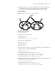
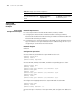
■ VLAN 6 on Switch C is an isolate-user-VLAN which includes the uplink port
Ethernet1/0/1 and two secondary VLANs: VLAN 3 and VLAN 4. VLAN 3
includes port Ethernet1/0/3, and VLAN 4 includes port Ethernet1/0/4.
Network diagram
Figure 32 Diagram for isolate-user-VLAN configuration
Configuration procedure
■ Configure Switch B
# Configure the isolate-user-VLAN
<SwitchB> system-view
[SwitchB] vlan 5
[SwitchB-vlan5] isolate-user-vlan enable
# Configure the secondary VLAN.
[SwitchB-vlan5] quit
[SwitchB] vlan 3
[SwitchB-vlan3] quit
[SwitchB] vlan 2
# Add port Ethernet1/0/2 to the isolate-user-VLAN and the secondary VLAN, and
configure the port to untag the VLAN packets.
[SwitchB-vlan2] quit
[SwitchB] interface Ethernet 1/0/2
[SwitchB-Ethernet1/0/2] port link-type hybrid
[SwitchB-Ethernet1/0/2] port hybrid vlan 3 untagged
[SwitchB-Ethernet1/0/2] port hybrid vlan 5 untagged
[SwitchB-Ethernet1/0/2] port hybrid pvid vlan 3
# Add port Ethernet1/0/5 to the isolate-user-VLAN and the secondary VLAN, and
configure the port to untag the VLAN packets.
[SwitchB-Ethernet1/0/2] quit
[SwitchB] interface Ethernet 1/0/5
[SwitchB-Ethernet1/0/5] port link-type hybrid
[SwitchB-Ethernet1/0/5] port hybrid vlan 2 untagged
Switch C
Switch A
Switch C
E1/0/1
E1/0/3
E1/0/4
E1/0/1
Switch B
E1/0/2 E1/0/5
E1/0/1
E1/0/3
E1/0/4
E1/0/1
Switch B
E1/0/2 E1/0/5
Switch CSwitch C
E1/0/1
E1/0/3
E1/0/4
Switch B
E1/0/1
E1/0/3
E1/0/4
Switch B
VLAN 5
VLAN 6
VLAN 3 VLAN 2 VLAN 3 VLAN 4
Switch C
Switch A
Switch C
E1/0/1
E1/0/3
E1/0/4
E1/0/1
Switch B
E1/0/2 E1/0/5
E1/0/1
E1/0/3
E1/0/4
E1/0/1
Switch B
E1/0/2 E1/0/5
Switch CSwitch C
E1/0/1
E1/0/3
E1/0/4
Switch B
E1/0/1
E1/0/3
E1/0/4
Switch B
VLAN 5
VLAN 6
VLAN 3 VLAN 2 VLAN 3 VLAN 4