
3Com Switch 7750 Configuration Guide Guide


118 CHAPTER 13: SUPER VLAN
Super VLAN
Configuration
Example
Super VLAN
Configuration Example
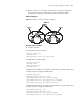
Network Requirements
■ Create super VLAN 10 and sub VLANs VLAN 2, VLAN 3, VLAN 5.
■ Configure ports Ethernet1/0/1 and Ethernet1/0/2 to belong to VLAN 2,
Ethernet1/0/3 and Ethernet1/0/4 to belong to VLAN 3 and Ethernet1/0/5 and
Ethernet1/0/6 to belong to VLAN 5.
■ Configure Layer 3 connectivity between sub VLANs, and all sub VLANs use the
Layer 3 interface of the super VLAN (with the IP address being 10.110.1.1) as
the gateway to communicate with the outside.
Network diagram
Omitted
Configuration procedure
# Create VLAN 10, and enable the super VLAN function on it.
<SW7750> system-view
[SW7750] vlan 10
[SW7750-vlan10] supervlan
# Create VLAN2, VLAN3, and VLAN5, and add corresponding ports to them.
[SW7750-vlan10] quit
[SW7750] vlan 2
[SW7750-vlan2] port Ethernet 1/0/1 Ethernet 1/0/2
[SW7750-vlan2] quit
[SW7750] vlan 3
[SW7750-vlan3] port Ethernet 1/0/3 Ethernet 1/0/4
[SW7750-vlan3] quit
[SW7750] vlan 5
[SW7750-vlan5] port Ethernet 1/0/5 Ethernet 1/0/6
# Configure the mapping between the super VLAN and the sub VLAN.
[SW7750-vlan5] quit
[SW7750] vlan 10
[SW7750-vlan10] subvlan 2 3 5
# Create the Layer 3 interface of the super VLAN, and configure an IP address for
it.
Tabl e 64 Display super VLAN configuration
Operation Command Description
Display the mapping between
the super VLAN and the sub
VLAN
display supervlan [
supervlan-id ]
The display command can be
executed in any view.