
3Com Switch 7750 Configuration Guide Guide

138 CHAPTER 16: IPX CONFIGURATION
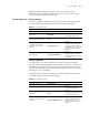
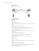
Network diagram
Figure 36 IPX network diagram
Configuration procedure
1 Configure Switch A.
# Enable IPX.
<SW7750> system-view
[SW7750] ipx enable
# Assign the network number 2 to VLAN interface 2 to enable IPX on the VLAN
interface.
[SW7750] interface Vlan-interface 2
[SW7750-Vlan-interface2] ipx network 2
# Set the packet encapsulation format to Ethernet_II on VLAN interface 2.
[SW7750-Vlan-interface2] ipx encapsulation ethernet-2
[SW7750-Vlan-interface2] quit
# Assign the network number 1000 to VLAN interface 1 to enable IPX on the
VLAN interface.
[SW7750] interface Vlan-interface 1
[SW7750-Vlan-interface1] ipx network 1000
# Configure a static route with the destination network number 3.
[SW7750-Vlan-interface1] quit
[SW7750] ipx route-static 3 1000.00e0-fc01-0001 tick 7 hop 2
2 Configure Switch B.
# Enable IPX.
[SW7750] ipx enable
# Assign the network number 3 to VLAN interface 2 to enable IPX on the VLAN
interface.
[SW7750] interface Vlan-interface 2
[SW7750-Vlan-interface2] ipx network 3
# Set the packet encapsulation format to Ethernet_SNAP on VLAN interface 2.
[SW7750-Vlan-interface2] ipx encapsulation snap
[SW7750-Vlan-interface2] quit
Switch A
Server
Client
2.00e0-fc01-0000
3.00e0-fc01-0001
VLAN interface 2
Switch B
VLAN intefae 1
VLAN interface 1
VLAN interface 2
1000.00e0-fc01-00011000.00e0-fc01-0000
IPX
Switch A
Server
Client
2.00e0-fc01-0000
3.00e0-fc01-0001
VLAN interface 2
Switch B
VLAN intefae 1
VLAN interface 1
VLAN interface 2
1000.00e0-fc01-00011000.00e0-fc01-0000
IPX