
3Com Switch 7750 Configuration Guide Guide

242 CHAPTER 29: MSTP CONFIGURATION
n
In a network that contains switches with both GVRP and MSTP employed, GVRP
packets are forwarded along the CIST. If you want to broadcast packets of a
specific VLAN through GVRP, be sure to map the VLAN to the CIST when
configuring the MSTP VLAN mapping table (The CIST of a network is the spanning
tree instance numbered 0.)
Prerequisites The status of the switches in the spanning trees is determined. That is, the status
(root, branch, or leaf) of each switch in each spanning tree instance is determined.
MST Region
Configuration
Refer to “MST Region Configuration”.
MSTP Operation Mode
Configuration
Refer to “MSTP Operation Mode Configuration”.
Timeout Time Factor
Configuration
Refer to “Timeout Time Factor Configuration”.
Maximum Transmitting
Speed Configuration
Refer to “Maximum Transmitting Speed Configuration”.
Edge Port Configuration Refer to “Edge Port Configuration”.
Path Cost Configuration The path cost parameters reflects the link rates on ports. For a port on an
MSTP-enabled switch, the path cost may differ with spanning tree instance. You
can enable flows of different VLANs to travel along different physical links by
configuring appropriate path costs on ports, so that load balancing can be
achieved by VLANs.
Path cost can be determined by switch or through manual configuration.
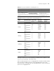
Standards for calculating path costs of ports
Currently, a switch can calculate the path costs of ports based on one of the
following standards:
■ dot1d-1998: Adopts the IEEE 802.1D-1998 standard to calculate the default
path costs of ports.
■ dot1t: Adopts the IEEE 802.1t standard to calculate the default path costs of
ports.
■ legacy: Adopts the standard defined by private to calculate the default path
costs of ports.
Point-to-point link related
configuration
Optional
“Point-to-point Link-Related
Configuration”
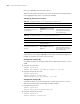
Table 172 Leaf node configuration
Operation Remarks Related section