
3Com Switch 7750 Configuration Guide Guide

MSTP Implementation Example 257
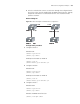
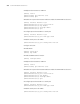
Network diagram
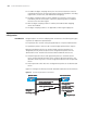
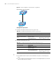
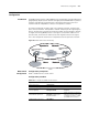
Figure 61 Network diagram for implementing MSTP
n
The "Permit:" shown in Figure 61 means the corresponding link permits packets of
specific VLANs.
Configuration procedure
1 Configure Switch A.
# Enter MST region view.
<SW7750> system-view
[SW7750] stp region-configuration
# Configure the MST region.
[SW7750-mst-region] region-name example
[SW7750-mst-region] instance 1 vlan 10
[SW7750-mst-region] instance 3 vlan 30
[SW7750-mst-region] instance 4 vlan 40
[SW7750-mst-region] revision-level 0
# Activate the settings of the MST region.
[SW7750-mst-region] active region-configuration
# Specify Switch A as the root bridge of spanning tree instance 1.
[SW7750] stp instance 1 root primary
2 Configure Switch B.
# Enter MST region view.
<SW7750> system-view
[SW7750] stp region-configuration
# Configure the MST region.
[SW7750-mst-region] region-name example
[SW7750-mst-region] instance 1 vlan 10
[SW7750-mst-region] instance 3 vlan 30
[SW7750-mst-region] instance 4 vlan 40
[SW7750-mst-region] revision-level 0
Switch A
Switch C
Switch B
Switch D
Permit :
VLAN 10, 20
Permit :
VLAN 10, 20
Permit :
VLAN 20, 30
Permit :
VLAN 20, 30
Permit :all VLAN
Permit :VLAN 20, 40
Switch A
Switch C
Switch B
Switch D
Permit :
VLAN 10, 20
Permit :
VLAN 10, 20
Permit :
VLAN 20, 30
Permit :
VLAN 20, 30
Permit :all VLAN
Permit :VLAN 20, 40