
3Com Switch 7750 Configuration Guide Guide

BPDU Tunnel Configuration Example 259
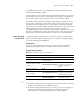
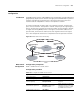
■ Switch C and Switch D connect to each other through the configured trunk
port of the switch, and are enabled with the BPDU Tunnel function. Thereby
transparent transmission is realized between the user’s network and the
operator’s network.
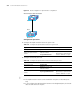
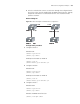
Network diagram
Figure 62 Network diagram for BPDU Tunnel configuration
Configuration procedure
1 Configure Switch A.
# Enable RSTP.
<SW7750> system-view
[SW7750] stp enable
# Add port Ethernet0/1 to VLAN 10.
[SW7750] vlan 10
[SW7750-Vlan10] port Ethernet 0/1
2 Configure Switch B.
# Enable RSTP.
<SW7750> system-view
[SW7750] stp enable
# Add port Ethernet0/1 to VLAN 10.
[SW7750] vlan 10
[SW7750-Vlan10] port Ethernet 0/1
3 Configure Switch C.
# Enable MSTP.
<SW7750> system-view
[SW7750] stp enable
# Enable the BPDU Tunnel function.
[SW7750] vlan-vpn tunnel
Switch C
Switch A E 0/1
Switch D
Switch B
E 1/0/2
E 0/1
E 1/0/1
Switch C
Switch A
E 1/0/1
E 0/1
Switch D
Switch B
E 0/1
E 1/0/2
Switch C
Switch A E 0/1
Switch D
Switch B
E 1/0/2
E 0/1
E 1/0/1
Switch C
Switch A
E 1/0/1
E 0/1
Switch D
Switch B
E 0/1
E 1/0/2