
3Com Switch 7750 Configuration Guide Guide


Routing Management Policy 263
■ Direct route: The router is directly connected to the network where the
destination resides.
■ Indirect route: The router is not directly connected to the network where the
destination resides.
In order to avoid an oversized routing table, you can set a default route. All the
packets for which the router fails to find a matching entry in the routing table will
be forwarded through this default route.
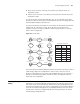
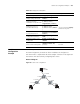
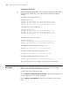
As shown in Figure 64, the number in each network cloud indicates the network
address and "R" represents a router. The router R8 is connected to three
networks, and so it has three IP addresses and three physical ports. Its routing
table is shown in
Figure 64.
Figure 64 Routing table
The 3Com Switch 7750 Family Ethernet Switches (hereinafter referred to as Switch
7750 Family) support the configuration of static routes as well as a series of
dynamic routing protocols such as RIP, OSPF and BGP. Moreover, the switches in
operation can automatically obtain some direct routes according to interface
status and user configuration.
Routing Management
Policy
On the Switch 7750 Family, you can manually configure a static route to a certain
destination, or configure a dynamic routing protocol to make the switch interact
with other routers in the internetwork and find routes by routing algorithm. On
the Switch 7750 Family, the static routes configured by the user and the dynamic
routes discovered by routing protocols are managed uniformly. The static routes
and the routes learned or configured by different routing protocols can also be
shared among routing protocols.
10.0.0.0
11.0.0.0
12.0.0.0
13.0.0.0
14.0.0.0
15.0.0.0
16.0.0.0
R8
2
10.0.0.1
1
11.0.0.1
3
13.0.0.4
R2
R3
R5
R6
R7
R1
R4
10.0.0.2
16.0.0.316.0.0.1
16.0.0.2
13.0.0.3
15.0.0.1
15.0.0.2
14.0.0.1
14.0.0.2
13.0.0.2
13.0.0.1
12.0.0.1
12.0.0.2
12.0.0.3
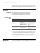
Routing table of router R8
Destination
network
10.0.0.0
Next hop Interface
10.0.0.1 2
11.0.0.0 11.0.0.1 1
12.0.0.0 11.0.0.2 1
11.0.0.2
13.0.0.0 13.0.0.4 3
14.0.0.0 13.0.0.2 3
15.0.0.0 13.0.0.2 3
16.0.0.0 10.0.0.2 2
10.0.0.0
11.0.0.0
12.0.0.0
13.0.0.0
14.0.0.0
15.0.0.0
16.0.0.0
R8
2
10.0.0.1
1
11.0.0.1
3
13.0.0.4
R2
R3
R5
R6
R7
R1
R4
10.0.0.2
16.0.0.316.0.0.1
16.0.0.2
13.0.0.3
15.0.0.1
15.0.0.2
14.0.0.1
14.0.0.2
13.0.0.2
13.0.0.1
12.0.0.1
12.0.0.2
12.0.0.3
Routing table of router R8
Destination
network
10.0.0.0
Next hop Interface
10.0.0.1 2
11.0.0.0 11.0.0.1 1
12.0.0.0 11.0.0.2 1
11.0.0.2
13.0.0.0 13.0.0.4 3
14.0.0.0 13.0.0.2 3
15.0.0.0 13.0.0.2 3
16.0.0.0 10.0.0.2 2