
3Com Switch 7750 Configuration Guide Guide


Troubleshooting RIP Configuration 285
correctly to ensure the interworking between the networks connected to SwitchC,
SwitchA and SwitchB.
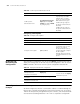
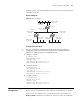
Network diagram
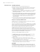
Figure 67 RIP configuration
Configuration procedure
n
Only the configuration related to RIP is listed below. Before the following
configuration, make sure the Ethernet link layer works normally and the IP
addresses of VLAN interfaces are configured correctly.
1 Configure SwitchA:
# Configure RIP.
<SwitchA>system-view
[SwitchA] rip
[SwitchA-rip] network 110.11.2.0
[SwitchA-rip] network 155.10.1.0
2 Configure SwitchB:
# Configure RIP.
<SwitchB>system-view
[SwitchB] rip
[SwitchB-rip] network 196.38.165.0
[SwitchB-rip] network 110.11.2.0
3 Configure SwitchC:
# Configure RIP.
<SwitchC>system-view
[SwitchC] rip
[SwitchC-rip] network 117.102.0.0
[SwitchC-rip] network 110.11.2.0
Troubleshooting RIP
Configuration
Symptom: The layer 3 switch cannot receive any RIP update packet when the
physical connection between the switch and the peer routing device is normal.
Solution: RIP is not enabled on the corresponding interface (for example, the
undo rip work command is executed on the interface) or RIP is not enabled by
Ethernet
Network address:
110.11.2.2/24
Network address:
117.102.0.0/16
Network address:
196.38.165.0/24
Interface address:
117.102.0.1/16
Interface address:
155.10.1.1/24
Network address:
155.10.1.0/24
Interface address:
196.38.165.1/24
Switch A
Switch B
Switch C
Interface address:
Interface address:
110.11.2.1/24
110.11.2.3/24