
3Com Switch 7750 Configuration Guide Guide


312 CHAPTER 34: OSPF CONFIGURATION
■ Ensure that the backbone area is connected to all the other areas.
■ Ensure that no virtual link passes through a stub area.
Global fault removal: If OSPF still cannot discover the remote routes after the
above procedure is performed, check the following configurations:
■ If two or more areas are configured on a router, at least one area should be
configured to be connected to the backbone area.
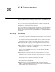
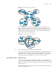
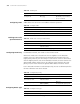
As shown in Figure 72, RTA and RTD are configured to belong to only one area,
whereas RTB (Area 0 and Area 1) and RTC (Area 1 and Area 2) are configured to
belong to two areas. RTB also belongs to area 0, which meets the requirement.
However, none of the areas of RTC is Area 0. Therefore, a virtual link should be set
up between RTC and RTB. Ensure that Area 2 and Area 0 (backbone area) are
interconnected.
Figure 72 OSPF area
■ A virtual link cannot pass through a stub area. The backbone area (Area 0)
cannot be configured as a stub area. So, if a virtual link has been set up
between RTB and RTC, neither Area 1 nor Area 0 can be configured as a stub
area. In
Figure 72, only Area 2 can be configured as a stub area.
■ A router in a stub area cannot receive external routes.
■ The backbone area must guarantee the connectivity between various nodes.
RTA RTB RTC RTD
Area 0 Area 1 Area 2
RTA RTB RTC RTD
Area 0 Area 1 Area 2