
3Com Switch 7750 Configuration Guide Guide


IS-IS Overview 315
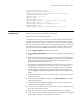
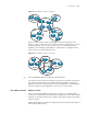
Figure 73 An example of the IS-IS topology I
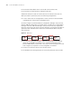
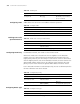
Figure 74 shows another network topology running the IS-IS protocol. The
Level-1-2 routers connect the Level-1 and Level-2 routers, and also forms the IS-IS
backbone together with the Level-2 routers. There is no area defined as the
backbone in this topology. The backbone is composed of all contiguous Level-2
routers which can reside in different areas.
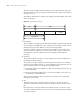
Figure 74 An example of the IS-IS topology II
n
The IS-IS backbone does not need to be a particular Area.
This network scenario shows the difference between IS-IS and OSPF. In OSPF, the
routes between areas must be forwarded though the backbone, and the SPF
algorithm is used in the same area. But in IS-IS, SPF algorithm is used to generate
the shortest path tree (SPT) regardless of the Level-1 or Level-2 router.
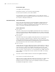
IS-IS Address Structure Address structure
The ISO uses the NSAP address format shown in Figure 75. The NSAP address
consists of the initial domain part (IDP) and the domain specific part (DSP). The IDP
equals to the network id field in the IP address, and the DSP equals to the subnet
and host id field.
The IDP, defined by ISO, includes the authority and format identifier (AFI) and the
initial domain identifier (IDI).
Area 5
Area 1
Area 2
Area 4
Area 3
L2
L2
L1
L1
L1
L1
L1/2
L1/2
L1/2
L1/2
L2 L2
L1
L1
Area 5
Area 1
Area 2
Area 4
Area 3
L2
L2
L1
L1
L1
L1
L1/2
L1/2
L1/2
L1/2
L2 L2
L1
L1
Area 3
Area 4
Area 2
Area 1
L1
L2
L1/L2
L1/L2
L2
L2
L1
L1
Area 3
Area 4
Area 2
Area 1
L1
L2
L1/L2
L1/L2
L2
L2
L1
L1