
3Com Switch 7750 Configuration Guide Guide

356 CHAPTER 36: BGP CONFIGURATION
[SwitchB-bgp] peer 172.68.10.1 group confed1001 as-number 1001
[SwitchB-bgp] group confed1003 external
[SwitchB-bgp] peer 172.68.10.3 group confed1003 as-number 1003
# Configure SwitchC.
[SwitchC] bgp 1003
[SwitchC-bgp] confederation id 100
[SwitchC-bgp] confederation peer-as 1001 1002
[SwitchC-bgp] group confed1001 external
[SwitchC-bgp] peer 172.68.10.1 group confed1001 as-number 1001
[SwitchC-bgp] group confed1002 external
[SwitchC-bgp] peer 172.68.10.2 group confed1002 as-number 1002
[SwitchC-bgp] group ebgp200 external
[SwitchC-bgp] peer 156.10.1.2 group ebgp200 as-number 200
[SwitchC-bgp] group ibgp1003 internal
[SwitchC-bgp] peer 172.68.1.2 group ibgp1003
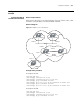
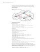
Configuring BGP RR Network requirements
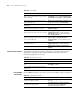
SwitchB receives an update packet passing through the EBGP, and transfers the
packet to SwitchC. SwitchC is configured as an RR with two clients SwitchB and
SwitchD. After SwitchC receives the routing update information, it reflects the
message to SwitchD. You need not to establish IBGP connection between SwitchB
and SwitchD, because SwitchC reflects information from SwitchC to SwitchD.
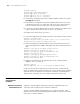
Network diagram
Figure 82 Diagram for configuring a BGP RR
Configuration procedure
1 Configure SwitchA.
[SwitchA] interface vlan-interface 2
[SwitchA-Vlan-interface2] ip address 192.1.1.1 255.255.255.0
[SwitchA-Vlan-interface2] interface Vlan-interface 100
[SwitchA-Vlan-interface100] ip address 1.1.1.1 255.0.0.0
[SwitchA-Vlan-interface100] quit
[SwitchA] bgp 100
[SwitchA-bgp] group ex external
IBGP IBGP
EBGP
Client
Client
Route reflector
VLAN 4
194.1.1.1/24
VLAN 3
193.1.1.1/24
VLAN 3
193.1.1.2/24
VLAN 4
194.1.1.2/24
VLAN 2
192.1.1.2/24
VLAN 2
192.1.1.1/24
AS100
AS200
Network
1.0.0.0
VLAN 100
1.1.1.1/8
Switch A
Switch B
Switch C
Switch D