
3Com Switch 7750 Configuration Guide Guide

358 CHAPTER 36: BGP CONFIGURATION
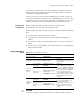
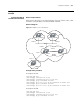
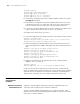
between SwitchA and SwitchB, and between SwitchA and SwitchC. IBGP is
running between SwitchB and SwitchC, and between SwitchB and SwitchD.
Network diagram
Figure 83 Diagram for BGP routing
Configuration procedure
1 Configure Switch A.
[SwitchA] interface Vlan-interface 2
[SwitchA-Vlan-interface2] ip address 192.1.1.1 255.255.255.0
[SwitchA] interface Vlan-interface 3
[SwitchA-Vlan-interface3] ip address 193.1.1.1 255.255.255.0
# Enable BGP
[SwitchA] bgp 100
# Specify the destination network for BGP routes.
[SwitchA-bgp] network 1.0.0.0
# Configure BGP peers.
[SwitchA-bgp] group ex192 external
[SwitchA-bgp] peer 192.1.1.2 group ex192 as-number 200
[SwitchA-bgp] group ex193 external
[SwitchA-bgp] peer 193.1.1.2 group ex193 as-number 200
[SwitchA-bgp] quit
# Configure the MED attribute of Switch A.
Create an access control list to permit routing information sourced from the
network 1.0.0.0.
[SwitchA] acl number 2000
[SwitchA-acl-basic-2000] rule permit source 1.0.0.0 0.255.255.255
[SwitchA-acl-basic-2000] rule deny source any
Define two routing policies, named apply_med_50 and apply_med_100
respectively. The first routing policy apply_med_50 configures the MED attribute
as 50 for network 1.0.0.0, and the second one apply_med_100 configures the
MED attribute for the network as 100.
[SwitchA] route-policy apply_med_50 permit node 10
[SwitchA-route-policy] if-match acl 2000
VLAN 4
194.1.1.2/24
VLAN 2
192.1.1.1/24
VLAN 3
193.1.1.1/24
VLAN 3
193.1.1.2/24
VLAN 5
195.1.1.2/24
VLAN 2
192.1.1.2/24
2.2.2.2
4.4.4.4
3.3.3.3
1.1.1.1
AS100
AS200
VLAN 4
194.1.1.1/24
VLAN 5
195.1.1.1/24
IBGP
IBGP
EBGP
EBGP
To network
1.0.0.0
To network
2.0.0.0
To network
4.0.0.0
To network
3.0.0.0
Switch A
Switch B
Switch C
Switch D