
3Com Switch 7750 Configuration Guide Guide


370 CHAPTER 37: IP ROUTING POLICY CONFIGURATION
IP Routing Policy
Configuration
Example
Configuring IP Routing
Policy
Network requirements
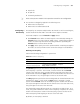
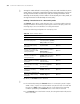
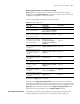
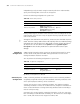
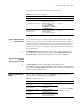
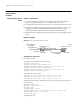
■ As shown in Figure 84, Switch A communicates with Switch B using OSPF
protocol. Switch A’s router ID is 1.1.1.1 and Switch B’s is 2.2.2.2.
■ Configure OSPF routing process on Switch A, and configure three static routes.
■ Configure a routing policy for Switch A to filter imported static routes. In this
example, the routes in 20.0.0.0 and 40.0.0.0 network segments can be
imported, but those in 30.0.0.0 network segment will be filtered out.
■ Display the OSPF routing table on Switch B and check if the routing policy takes
effect.
Network diagram
Figure 84 Filter routing information received
Configuration procedure
1 Configure SwitchA:
# Configure the IP addresses of the interfaces.
<SwitchA> system-view
[SwitchA] interface vlan-interface 100
[SwitchA-Vlan-interface100] ip address 10.0.0.1 255.0.0.0
[SwitchA] interface vlan-interface 200
[SwitchA-Vlan-interface200] ip address 12.0.0.1 255.0.0.0
[SwitchA-Vlan-interface200] quit
# Configure three static routes.
[SwitchA] ip route-static 20.0.0.1 255.0.0.0 12.0.0.2
[SwitchA] ip route-static 30.0.0.1 255.0.0.0 12.0.0.2
[SwitchA] ip route-static 40.0.0.1 255.0.0.0 12.0.0.2
# Enable the OSPF protocol and specify the ID of the area to which the interface 1
0.0.0.1
belongs.
<SwitchA> system-view
[SwitchA] router id 1.1.1.1
[SwitchA] ospf
[SwitchA-ospf-1] area 0
[SwitchA-ospf-1-area-0.0.0.0] network 10.0.0.0 0.255.255.255
[SwitchA-ospf-1-area-0.0.0.0] quit
[Switch-ospf-1]quit
# Configure an ACL.
area 0
static 20.0.0.0/8
30.0.0.0/8
40.0.0.0/8
Router ID:
1.1.1.1
10.0.0.2/8
Switch A Switch B
Vlan-interface200
12.0.0.1/8
Router ID:
2.2.2.2
Vlan-interface100
10.0.0.1/8
Vlan-interface100
Area 0
static 20.0.0.0/8
30.0.0.0/8
40.0.0.0/8
Router ID:
1.1.1.1
10.0.0.2/8
Switch A Switch B
Vlan-interface200
12.0.0.1/8
Router ID:
2.2.2.2
Vlan
-interface100
10.0.0.1/8
Vlan-interface100