
3Com Switch 7750 Configuration Guide Guide

436 CHAPTER 44: PIM CONFIGURATION
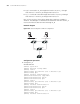
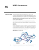
■ LS_B is connected to LS_A through Vlan-interface 10, to LS_C through
Vlan-interface 11 and to LS_D through Vlan-interface 12.
■ LS_C is connected to Host B through Vlan-interface 10, to LS_B through
Vlan-interface 11 and to LS_A through Vlan-interface 12.
Host A is the receiver of the multicast group whose multicast IP address is
225.0.0.1. Host B begins to send data to the destination 225.0.0.1 and LS_A
receives the multicast data from Host B through LS_B.
Network diagram
Figure 104 Network diagram for PIM-SM configuration
Configuration procedure
1 Configure LS_A
# Enable PIM-SM.
<SW7750> system-view
[SW7750] multicast routing-enable
[SW7750] vlan 10
[SW7750-vlan10] port Ethernet 1/0/2 to Ethernet 1/0/3
[SW7750-vlan10] quit
[SW7750] interface Vlan-interface 10
[SW7750-Vlan-interface10] igmp enable
[SW7750-Vlan-interface10] pim sm
[SW7750-Vlan-interface10] quit
[SW7750] vlan 11
[SW7750-vlan11] port Ethernet 1/0/4 to Ethernet 1/0/5
[SW7750-vlan11] quit
[SW7750] interface Vlan-interface 11
[SW7750-Vlan-interface11] pim sm
[SW7750-Vlan-interface11] quit
[SW7750] vlan 12
[SW7750-vlan12] port Ethernet 1/0/6 to Ethernet 1/0/7
[SW7750-vlan12] quit
[SW7750] interface Vlan-interface 12
LSD
LSB
LSC
LSA
HostA HostB
VLAN11 VLAN12
VLAN10
VLAN10
VLAN11
VLAN12
VLAN12 VLAN10
VLAN11