
3Com Switch 7750 Configuration Guide Guide

MSDP Configuration Example 455
Input queue size: 0, Output queue size: 0
Counters for MSDP message:
Count of RPF check failure: 0
Incoming/outgoing SA messages: 0/0
Incoming/outgoing SA requests: 0/0
Incoming/outgoing SA responses: 0/0
Incoming/outgoing data packets: 0/0
Configuration Example
of Anycast RP
Application
Network requirements
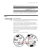
Each PIM-SM network is a single-BSR administrative domain, with multiple
multicast sources (S) and receivers. With Anycast RP configured in each PIM-SM
domain, when a new member joins the multicast group, the switch directly
connected to the receiver can send a Join message to the nearest RP on the
topology.
The PIM-SM network implements OSPF to provide unicast routes and establish
MSDP peering relationship between Switch C and Switch D. Meanwhile, the
Loopback10 interfaces of Switch C and Switch D play the roles of C-BSR and C-RP.
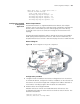
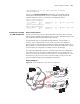
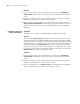
Network diagram
Figure 110 Network diagram for Anycast RP configuration
Configuration procedure
1 Configure interface IP addresses and unicast routing protocols on the switches.
In the PIM-SM domain, configure the interface IP addresses on the switches and
interconnect the switches through OSPF. Configure the IP address and mask of
each interface according to
Figure 109. The details are omitted here.
2 Enable multicast and configure PIM-SM.
# Enable multicast on SwitchC and enable PIM-SM on all interfaces. The
configuration
procedures on other switches are similar to that on SwitchC. The
details
are omitted here.
<SwitchC> system-view
[SwitchC] multicast routing-enable