
3Com Switch 7750 Configuration Guide Guide
458 CHAPTER 45: MSDP CONFIGURATION
Configuration procedure
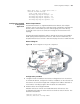
1 Configure the interface IP addresses and unicast routing protocols for each switch
Configure interface IP addresses for each switch, and configure OSPF for
interconnection between switches in each PIM-SM domain. Ensure the
network-layer interoperation among switches in PIM-SM1, the network-layer
interoperation between switches in PIM-SM2, and the network-layer
interoperation between switches in PIM-SM3, and ensure the dynamic update of
routing information between the switches in each PIM-SM domain is implemented
through a unicast routing protocol. Configure the IP address and subnet mask for
each interface as shown in
Figure 111. The detailed configuration steps are
omitted.
2 Enable multicast and enable PIM-SM on each interface.
# Enable multicast on all the switches, and enable PIM-SM on each interface.
The
configuration procedures on the other switches are similar to the
configuration
procedure on Switch C. So the configuration procedures on the
other
switches are omitted.
[SwitchC] multicast routing-enable
[SwitchC] interface vlan-interface 100
[SwitchC-Vlan-interface100] pim sm
[SwitchC-Vlan-interface100] quit
[SwitchC] interface vlan-interface 200
[SwitchC-Vlan-interface200] pim sm
[SwitchC-Vlan-interface200] quit
[SwitchC] interface vlan-interface 110
[SwitchC-Vlan-interface110] pim sm
[SwitchC-Vlan-interface110] quit
[SwitchC] interface Vlan-interface 101
[SwitchC-Vlan-interface101] pim sm
# Configure BSR administrative boundaries on Switch C, Switch D, and Switch F.
The
configuration procedures on Switch D and Switch F are similar to the
configuration
procedure on Switch C. So the configuration procedures are
omitted.
[SwitchC-Vlan-interface101] pim bsr-boundary
[SwitchC-Vlan-interface101] quit
[SwitchC] interface vlan-interface 110
[SwitchC-Vlan-interface110] pim bsr-boundary
[SwitchC-Vlan-interface110] quit
3 Configure the location of the Loopback 0 interface, C-BSRs, and C-RPs.
# Configure the location of the Loopback 0 interface, C-BSRs, and C-RPs on
Switch
C, Switch D, and Switch F respectively. The configuration procedures on
Switch
D and Switch F are similar to the configuration procedure on Switch C, so
the
configuration procedures are omitted.
[SwitchC] router id 1.1.1.1
[SwitchC] interface loopback 0
[SwitchC-LoopBack0] ip address 1.1.1.1 255.255.255.255
[SwitchC-LoopBack0] pim sm
[SwitchC-LoopBack0] quit
[SwitchC] pim
[SwitchC-pim] c-bsr loopback 0 32
[SwitchC-pim] c-rp loopback 0
[SwitchC-pim] quit