
3Com Switch 7750 Configuration Guide Guide


536 CHAPTER 50: VRRP CONFIGURATION
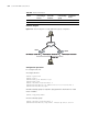
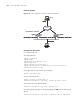
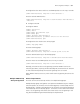
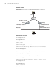
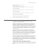
Network diagram
Figure 139 Network diagram for interface tracking configuration
Configuration procedure
■ Configure Switch A.
# Configure VLAN 2.
<LSW-A> system-view
[LSW-A] vlan 2
[LSW-A-vlan2] port Ethernet 1/0/6
[LSW-A-vlan2] quit
[LSW-A] interface Vlan-interface 2
[LSW-A-Vlan-interface2] ip address 202.38.160.1 255.255.255.0
[LSW-A-Vlan-interface2] quit
# Configure that the virtual router can be pinged.
[LSW-A] vrrp ping-enable
# Create a backup group.
[LSW-A] interface Vlan-interface 2
[LSW-A-Vlan-interface2] vrrp vrid 1 virtual-ip 202.38.160.111
# Set the priority for the backup group.
[LSW-A-Vlan-interface2] vrrp vrid 1 priority 110
# Set the authentication type for the backup group to md5, and the password to
abc123.
[LSW-A-Vlan-interface2] vrrp vrid 1 authentication-mode md5 abc123
Virtual IP address: 202.38.160.111
LSW-A
Hos t A
202.38.160.3
-
Vlan-interface2: 202.38.160.1
Internet
LSW-B
-
Vlan-interf ace2: 202.38.160.2
Hos t B
Virtual IP address: 202.38.160.111
Hos t A
202.38.160.3
-
Vlan-interface2: 202.38.160.1
Internet
-
Vlan-interf ace2: 202.38.160.2
Hos t B
Vlan-interface3: 10.100.10.2
10.2.3.1
Virtual IP address: 202.38.160.111
LSW-A
Hos t A
202.38.160.3
-
Vlan-interface2: 202.38.160.1
Internet
LSW-B
-
Vlan-interf ace2: 202.38.160.2
Hos t B
Virtual IP address: 202.38.160.111
Hos t A
202.38.160.3
-
Vlan-interface2: 202.38.160.1
Internet
-
Vlan-interf ace2: 202.38.160.2
Hos t B
Virtual IP address: 202.38.160.111
LSW-A
Hos t A
202.38.160.3
-
Vlan-interface2: 202.38.160.1
Internet
LSW-B
-
Vlan-interf ace2: 202.38.160.2
Hos t B
Virtual IP address: 202.38.160.111
Hos t A
202.38.160.3
-
Vlan-interface2: 202.38.160.1
Internet
-
Vlan-interf ace2: 202.38.160.2
Hos t B
Vlan-interface3: 10.100.10.2
10.2.3.1