
3Com Switch 7750 Configuration Guide Guide

Configuration Example 591
Configuration
Example
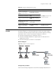
Network requirements
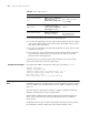
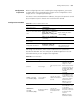
As shown in Figure 151, the Ethernet1/0/1 port of Switch A (a Switch 7750) is
connected to Switch B (acting as a DHCP relay). A network segment containing
some DHCP clients is connect to the Ethernet 1/0/2 port of Switch A.
■ The DHCP snooping function is enabled on Switch A.
■ The DHCP-Snooping-enabled device supports option 82 and option 82 is
enabled on the switch.
■ The Ethernet1/0/1 port of Switch A is a trusted port.
Network diagram
Figure 151 DHCP-Snooping configuration
Configuration procedure
Perform the following configuration on the DHCP-Snooping-enabled Switch A.
Table 462 Display and debug DHCP-Snooping
Operation Command Description
Display the IP/MAC mapping
relations recorded by the
DHCP-Snooping-enabled
switch
display dhcp-snooping
The display command can be
executed in any view
Display DHCP-Snooping status
and trusted port information
display dhcp-snooping
trust
Display the total number of
DHCP-Snooping binding table
entries
display dhcp-snooping
count
Display the DHCP-Snooping
binding table entries of the
specified VLAN
display dhcp-snooping vlan
{ vlan-list | all }
Clear the IP/MAC mapping
relations recorded by the
DHCP-Snooping-enabled
switch
reset dhcp-snooping [
ip-address ]
The reset command can be
executed in user view
Internet
DHCP Client
DHCP Client
DHCP Client
Ethernet
DHCP Client
DHCP Server
Switch B
(DHCP Relay)
Internet
DHCP Client
DHCP Client
DHCP Client
EthernetEthernet
DHCP Client
Switch A
(DHCP-Snooping)
Internet
DHCP Client
DHCP Client
DHCP Client
Ethernet
DHCP Client
DHCP Server
Switch B
(DHCP Relay)
Internet
DHCP Client
DHCP Client
DHCP Client
EthernetEthernet
DHCP Client
Switch A
(DHCP-Snooping)