
3Com Switch 7750 Configuration Guide Guide


654 CHAPTER 59: MIRRORING CONFIGURATION
n
■ You can configure only one reflector port of a remote source mirroring group
or one destination port of a local mirroring group on each centralized I/O
Module. As for the distributed system, you can configure only one reflector
port of a remote source mirroring group or one destination port of a local
mirroring group for the whole system. Only one mirroring destination I/O
Module can be configured for the centralized or distributed system, and can be
referenced by only one local mirroring group.
■ If you want to mirror the tagged packets, you need to configure VLAN VPN on
the reflector port.
■ For the reflector port can not forward traffic as a normal port does, you are
recommended to configure the port that is not in use to be the reflector port
and not to perform other configurations on this port.
Configuring the intermediate switch
Configuring an intermediate switch is the same as configuring RSPAN on the
intermediate switch. Refer to
“Configuring RSPAN on the intermediate switch” for
detail.
Configuring the destination switch
Configuring a destination switch is the same as configuring RSPAN on the
destination switch. Refer to
“Configuring RSPAN on the destination switch”.
Configuration example
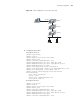
1 Network requirements:
■ Switch A is connected to the data detect device through GigabitEthernet 1/0/2.
■ GigabitEthernet 1/0/1, the relay port of Switch A, is connected to
GigabitEthernet 1/0/1, the relay port of Switch B.
■ GigabitEthernet 1/0/2, the relay port of Switch B, is connected to
GigabitEthernet 1/0/1, the relay port of Switch C.
■ GigabitEthernet 1/0/2, the port of Switch C, is connected to the 10.1.1.1/24
network segment.
Use the remote traffic mirroring function to mirror the packets from the
10.1.1.1/24 network segment to GigabitEthernet 1/0/2, the port of Switch A, so
that the data detect device can monitor the traffic:
■ Define VLAN10 as remote-probe VLAN.
■ Define Switch A as the destination switch; configure GigabitEthernet 1/0/2, the
port that is connected to the data detect device, as the destination port for
remote mirroring. Set GigabitEthernet1/0/2 to an Access port, where LACP
must be disabled and STP is recommended to be disabled.
■ Define Switch B as the intermediate switch.
■ Define Switch C as the source switch, GigabitEthernet 1/0/3 as the reflector
port. Set GigabitEthernet 1/0/3 to an Access port, with STP and LACP disabled.
Configure the traffic mirroring function on GigabitEthernet 1/0/2.
2 Network diagram