
3Com Switch 7750 Configuration Guide Guide

664 CHAPTER 60: POE CONFIGURATION
PoE Configuration
Example
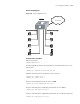
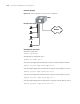
Networking requirements
■ Two PoE-enabled boards are installed in slot 3 and 5 on a Switch 7757.
■ Online upgrade the PSE processing software of the PoE board in slot 5 of the
Switch 7757.
■ Ethernet3/0/1 to Ethernet3/0/48 are connected with IP phones and
Ethernet5/0/1 to Ethernet5/0/48 are connected with access point (AP) devices.
■ The IP phones are connected to Ethernet3/0/1 through Ethernet3/0/48, and
access point (AP) devices are connected to Ethernet5/0/1 through
Ethernet5/0/48.
■ PoE need not be enabled on the IP phones connected to Ethernet3/0/1 and
Ethernet3/0/48.
■ Ethernet3/0/48 requires high priority.
■ Set the PoE management mode of slot 3 to auto.
■ Slot 3 is supplied with 400 W of power and slot 5 is supplied with full power
(namely, 806 W).
■ Enable PoE-compatibility detection on the PoE board in slot 3.
■ The input power of the AP device connected the Ehternet5/0/15 port cannot
be greater than 9 W.
Tabl e 525 Display and maintain PoE
Operation Command Description
Display the PoE status of a
specific port or all ports of the
switch
display poe interface {
interface-type
interface-number | all }
You can execute the display
command in any view
Display the PoE power
information of a specific port
or all ports of the switch
display poe interface
power { interface-type
interface-number | all }
Display the PSE parameters display poe powersupply
Display the power supply
status of each board and the
power that the board supplies
display poe pse