
3Com Switch 7750 Configuration Guide Guide

670 CHAPTER 61: POE PSU SUPERVISION CONFIGURATION
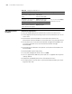
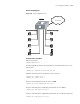
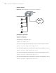
Network diagram
Figure 169 Network diagram for PoE supervision configuration
Configuration procedure
# Enter the system view.
<SW7750> system-view
# Enable PoE on the board in slot 3.
[SW7750] poe enable slot 3
# Set the overvoltage alarm threshold of AC input for the PoE PSUs to 264.0 V.
[SW7750] poe-power input-thresh upper 264.0
# Set the undervoltage alarm threshold of AC input for the PoE PSUs to 181.0 V.
[SW7750] poe-power input-thresh lower 181.0
# Set the overvoltage alarm threshold of DC output for the PoE PSUs to 55.0 V.
[SW7750] poe-power output-thresh upper 55.0
# Set the undervoltage alarm threshold of DC output for the PoE PSUs to 47.0 V.
[SW7750] poe-power output-thresh lower 47.0
Ethernet3/0/1~Ethernet3/0/48
IP Phone
Network
S6506
IP Phone
IP Phone
IP Phone
Ethernet3/0/1~Ethernet3/0/48
IP Phone
Network
S6506
IP Phone
IP Phone
IP Phone