
3Com Switch 7750 Configuration Guide Guide


686 CHAPTER 64: SNMP CONFIGURATION
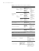
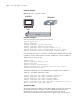
Network diagram
Figure 173 Network diagram for SNMP
Network procedure
# Set the community name, group name and user.
<SW7750> system-view
[SW7750] snmp-agent
[SW7750] snmp-agent sys-info version all
[SW7750] snmp-agent community write public
[SW7750] snmp-agent mib-view include internet 1.3.6.1
[SW7750] snmp-agent group v3 managev3group write-view internet
[SW7750] snmp-agent usm-user v3 managev3user managev3group
# Set the VLAN interface 2 as the interface used by NMS. Add port Ethernet1/0/2
to VLAN 2. This port will be used for network management. Set the IP address of
VLAN interface 2 as 10.10.10.2.
[SW7750] vlan 2
[SW7750-vlan2] port Ethernet 1/0/2
[SW7750-vlan2] quit
[SW7750] interface Vlan-interface 2
[SW7750-Vlan-interface2] ip address 10.10.10.2 255.255.255.0
[SW7750-Vlan-interface2] quit
# Enable the SNMP agent to send Trap packets to the NMS whose IP address is
10.10.10.1. The SNMP community is public.
[SW7750] snmp-agent trap enable standard authentication
[SW7750] snmp-agent trap enable standard coldstart
[SW7750] snmp-agent trap enable standard linkup
[SW7750] snmp-agent trap enable standard linkdown
[SW7750] snmp-agent target-host trap address udp-domain 10.10.10.1 u
dp-port
5000 params securityname public
Configuring NMS
The Switch 7750 Family supports 3Com’s NMS. SNMP V3 adopts user name and
password authentication. In [3Com's Network Management Authentication
Parameter], you need to set a user name, choose security level, and set
authorization mode, authorization password, encryption mode, and encryption
Ethernet
NMS
10.10.10.1
10.10.10 .2
Ethernet
NMS
10.10.10.1
10.10.10 .2