
3Com Switch 7750 Configuration Guide Guide


Configuring Queue Traffic Monitoring 807
to be detected. Users can then locate, solve, and log link problems by monitoring
the peer devices through the received ARP response packets.
n
This function requires no Layer 3 device existing between the local peer and the
remote peer.
Layer 3 Connectivity
Detection Configuration
Task
n
Before performing this configuration, make sure the physical link between the
local peer and the remote peer is correct, and the related VLAN interfaces are
assigned with correct IP addresses.
Layer 3 Connectivity
Detection Configuration
Example
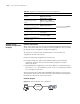
Network requirements
■ The physical link between the local peer and the remote peer is correct. The
local peer port that is used to connect is Ethernet4/0/1.
■ The IP address of the lay 3 interface of the remote peer is 1.1.1.1.
Configuration procedure
# Enter system view.
<SW7750> system-view
[SW7750]
# Enter Ethernet interface view.
[SW7750] interface Ethernet 4/0/1
# Enable Layer 3 connectivity detection on Ethernet4/0/1 interface and specify the
IP address of the device (1.1.1.1) to be detected.
[SW7750-Ethernet4/0/1] uplink monitor ip 1.1.1.1
Configuring Queue
Traffic Monitoring
Upon enabling queue traffic monitoring on a switch, the switch monitors the
queue traffic and relieves blocks in the output queue of its interfaces.
The criterion used to distinguish a block is that the queue is full, and the traffic of
the corresponding interface is less than the specified threshold.
Table 625 Configure Layer 3 connectivity detection
Operation Command Description
Enter system view system-view -
Enter Ethernet interface view
interface interface-type
interface-number
-
Enable Layer 3 connectivity
detection function
uplink monitor ip ip-address Required
Display information about
Layer 3 connectivity between
the local device and the
remote device.
display uplink monitor
Optional
You can execute the display
command in any view.