
3Com Switch 7750 Configuration Guide


Displaying and Debugging IPX 145
Displaying and
Debugging IPX
After the above-mentioned configuration, use the display command in any view
to view the running of IPX and to verify the effect of the configuration.
Use the reset command in user view to clear the IPX statistics.
IPX Configuration
Example
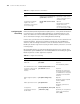
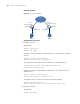
Network requirements
Through an IPX network, Switch A with the node address of 000f-e20f-0000 is
connected to Switch B with the node address of 000f-e20f-0001.
There is a server installed with NetWare 4.1 and assigned the network number of
2. On the server, the packet encapsulation format is set to Ethernet_II. The client is
a PC with the network number of 3 and the packet encapsulation format of SNAP.
The server provides file service and printing service. The client accesses the file and
printing services provided by the server through the IPX network. The node
address of the server is 0000-0c91-f61f.
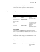
Enable the forwarding of
type 20 broadcast packets
ipx netbios-propagation Optional
By default, type 20 broadcast
packets are not forwarded
Table 92 Configure IPX forwarding
Operation Command Description
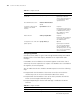
Table 93 Display and debug IPX
Operation Command Description
Display the information of IPX on
the VLAN interface
display ipx interface
[ Vlan-interface vlan-id ]
The display command
can be executed in any
view
Display the IP packet statistics display ipx statistics
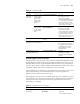
Display the IPX service
information table
display ipx service-table
[ inactive | name name |
network network |
order { network | type } | type
service-type ] [ verbose ]
Display the IPX routing
information
display ipx routing-table
[ network [ verbose ] |
protocol { default | direct | rip |
static } [ inactive | verbose ] |
statistics | verbose ]
Clear the IPX statistics reset ipx statistics The reset command
can be executed in
user view
Clear the IPX routing table
information
reset ipx routing-table
statistics protocol { all | default |
direct | rip | static }