
3Com Switch 7750 Configuration Guide


Shared VLAN Configuration Example 171
Shared VLAN
Configuration
Example
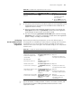
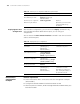
Network Requirements ■ The selective QinQ feature is enabled on the hybrid port Ethernet2/0/6 which is
connected to the customer network. The outer tag of VLAN 4 is inserted to
packets of VLAN 3 in the customer network, and these tagged packets are
transmitted to the service provider network through Ethernet2/0/15.
■ Configure VLAN 100 as the shared VLAN on the module in slot 2 in order that
any packet returned by the service provider can be unicast to the customer
network.
Network Diagram
Figure 49 Network diagram for Shared VLAN configuration
Configuration Procedure # Enable selective QinQ on Ethernet2/0/6. Refer to “Selective QinQ Configuration
Example” on page 167 for the details.
# Specify VLAN 100 as the shared VLAN on the module in slot 2.
<SW7750> system-view
[SW7750] vlan 100
[SW7750-vlan100] quit
[SW7750] shared-vlan 100 slot 2
# Add the ports of all the packets forwarded on the module in slot 2 to VLAN 100.
Refer to “Configuring a Port-Based VLAN” on page 97 for detailed configuration.
Table 104 Display shared VLAN
Operation Command Description
Display the shared VLANs
configured for all the I/O
Modules and Fabrics in the
system
display shared-vlan You can execute the
display command in any
view.
Customer
Provider
Eth2/0/6 (PVID=2)
Et h2/0 /15
VLAN 3
VLAN 4