
3Com Switch 7750 Configuration Guide

RIP Configuration Example 299
RIP Configuration
Example
Network requirements
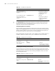
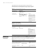
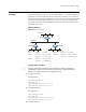
As shown in Figure 70, SwitchC is connected to subnet 117.102.0.0 through an
Ethernet port. SwitchA and SwitchB are connected to networks 155.10.1.0 and
196.38.165.0 respectively through Ethernet ports. SwitchC, SwitchA and SwitchB
are interconnected through Ethernet 110.11.2.0. It is required to configure RIP
correctly to ensure the interworking between the networks connected to SwitchC,
SwitchA and SwitchB.
Network diagram
Figure 70 RIP configuration
Configuration procedure
n
Only the configuration related to RIP is listed below. Before the following
configuration, make sure the Ethernet link layer works normally and the IP
addresses of VLAN interfaces are configured correctly.
1 Configure SwitchA:
# Configure RIP.
<SwitchA>system-view
[SwitchA] rip
[SwitchA-rip] network 110.11.2.0
[SwitchA-rip] network 155.10.1.0
2 Configure SwitchB:
# Configure RIP.
<SwitchB>system-view
[SwitchB] rip
[SwitchB-rip] network 196.38.165.0
[SwitchB-rip] network 110.11.2.0
3 Configure SwitchC:
Device Interface IP address Device Interface IP address
Switch A Vlan-int1 110.11.2.1/24 Switch B Vlan-int1 110.11.2.2/24
Vlan-int2 155.10.1.1/24 Vlan-int3 196.38.165.1/24
Switch C Vlan-int1 110.11.2.3/24
Vlan-int4 117.102.0.1/16
Switch A
Switch B
Switch C
Vlan-int 2
Ethernet
Vlan-int 4 Vlan-int 3
Vlan-int 1