
3Com Switch 7750 Configuration Guide

322 CHAPTER 34: OSPF CONFIGURATION
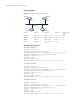
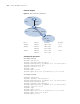
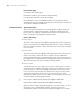
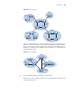
Network diagram
Figure 73 DR election based on OSPF priority
Configuration procedure
# Configure SwitchA.
<SwitchA> system-view
[SwitchA] interface Vlan-interface 1
[SwitchA-Vlan-interface1] ip address 196.1.1.1 255.255.255.0
[SwitchA-Vlan-interface1] ospf dr-priority 100
[SwitchA] router id 1.1.1.1
[SwitchA] ospf
[SwitchA-ospf-1] area 0
[SwitchA-ospf-1-area-0.0.0.0] network 196.1.1.0 0.0.0.255
# Configure SwitchB.
<SwitchB> system-view
[SwitchB] interface Vlan-interface 1
[SwitchB-Vlan-interface1] ip address 196.1.1.2 255.255.255.0
[SwitchB-Vlan-interface1] ospf dr-priority 0
[SwitchB] router id 2.2.2.2
[SwitchB] ospf
[SwitchB-ospf-1] area 0
[SwitchB-ospf-1-area-0.0.0.0] network 196.1.1.0 0.0.0.255
# Configure SwitchC.
<SwitchC> system-view
[SwitchC] interface Vlan-interface 1
[SwitchC-Vlan-interface1] ip address 196.1.1.3 255.255.255.0
[SwitchC-Vlan-interface1] ospf dr-priority 2
[SwitchC] router id 3.3.3.3
[SwitchC] ospf
[SwitchC-ospf-1] area 0
[SwitchC-ospf-1-area-0.0.0.0] network 196.1.1.0 0.0.0.255
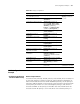
Device Interface IP address Router ID Interface DR
priority
Switch A Vlan-int1 196.1.1.1/24 1.1.1.1 100
Switch B Vlan-int1 196.1.1.2/24 2.2.2.2 0
Switch C Vlan-int1 196.1.1.3/24 3.3.3.3 2
Switch D Vlan-int1 196.1.1.4/24 4.4.4.4 1
DR
BDR
Switch A
Switch D
Switch CSwitch B
Vlan-int1
Vlan-int1
Vlan-int1
Vlan-int1