
3Com Switch 7750 Configuration Guide

326 CHAPTER 34: OSPF CONFIGURATION
■ If the network type is broadcast or NBMA, ensure that there is at least one
interface with a priority greater than zero.
■ If an area is set to a stub area, ensure that the area is set to a stub area for all
the routers connected to this area.
■ Ensure that the interface types of two neighboring routers are consistent.
■ If two or more areas are configured, ensure that at least one area is configured
as the backbone area; that is, the area ID of an area is 0.
■ Ensure that the backbone area is connected to all the other areas.
■ Ensure that no virtual link passes through a stub area.
Global fault removal: If OSPF still cannot discover the remote routes after the
above procedure is performed, check the following configurations:
■ If two or more areas are configured on a router, at least one area should be
configured to be connected to the backbone area.
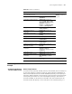
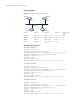
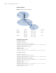
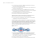
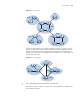
As shown in Figure 75, Router A and Router D are configured to belong to only
one area, whereas Router B (Area 0 and Area 1) and Router C (Area 1 and Area 2)
are configured to belong to two areas. Router B also belongs to area 0, which
meets the requirement. However, none of the areas of Router C is Area 0.
Therefore, a virtual link should be set up between Router C and Router B. Ensure
that Area 2 and Area 0 (backbone area) are interconnected.
Figure 75 OSPF area
■ A virtual link cannot pass through a stub area. The backbone area (Area 0)
cannot be configured as a stub area. So, if a virtual link has been set up
between RTB and RTC, neither Area 1 nor Area 0 can be configured as a stub
area. In Figure 75, only Area 2 can be configured as a stub area.
■ A router in a stub area cannot receive external routes.
■ The backbone area must guarantee the connectivity between various nodes.
Area 0
Area 1
Area 2
ABRABR
Transit Area
Virtual Link
Router A Router B Router C
Router D