
3Com Switch 7750 Configuration Guide

IS-IS Overview 329
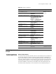
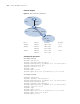
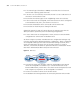
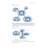
Figure 76 IS-IS topology I
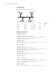
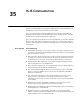
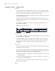
Figure 77 shows another IS-IS network topology. The Level-1-2 routers connect
the Level-1 and Level-2 routers, and form the IS-IS backbone together with the
Level-2 routers. There is no area defined as the backbone in this topology. The
backbone is composed of all contiguous Level-2 and Level-1-2 routers which can
reside in different areas.
Figure 77 IS-IS topology II
n
The IS-IS backbone does not need to be a specific area.
Both the IS-IS Level-1 and Level-2 routers use the SPF algorithm to generate the
shortest path tree (SPT).
Area 1
Area 3
Area 5
Area 4
Area 2
L1
L1/L2
L2
L2
L2
L1
L1/L2
L1/L2
L2
L1 L1
L1/L2
L1 L1
Area 1
L2
Area 3
Area 2
L1
L1
L1/L2
L2
L1/L2
L1
Area 4