
3Com Switch 7750 Configuration Guide


Configuration Example 373
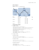
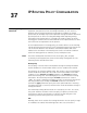
Network diagram
Figure 86 Diagram for BGP routing
Configuration procedure
1 Configure Switch A.
[SwitchA] interface Vlan-interface 2
[SwitchA-Vlan-interface2] ip address 192.1.1.1 255.255.255.0
[SwitchA] interface Vlan-interface 3
[SwitchA-Vlan-interface3] ip address 193.1.1.1 255.255.255.0
# Enable BGP
[SwitchA] bgp 100
# Specify the destination network for BGP routes.
[SwitchA-bgp] network 1.0.0.0
# Configure BGP peers.
[SwitchA-bgp] group ex192 external
[SwitchA-bgp] peer 192.1.1.2 group ex192 as-number 200
[SwitchA-bgp] group ex193 external
[SwitchA-bgp] peer 193.1.1.2 group ex193 as-number 200
[SwitchA-bgp] quit
# Configure the MED attribute of Switch A.
Device Interface IP address AS
Switch A Vlan-int 101 1.1.1.1/8 100
Vlan-int 2 192.1.1.1/24
Vlan-int 3 193.1.1.1/24
Switch B Vlan-int 2 192.1.1.2/24 200
Vlan-int 4 194.1.1.2/24
Switch C Vlan-int 3 193.1.1.2/24
Vlan-int 5 195.1.1.2/24
Switch D Vlan-int 4 194.1.1.1/24
Vlan-int 5 195.1.1.1/24
Switch A
AS 100
Vlan-int101
Switch C
AS 200
Switch B
Switch D
VLAN-int2
VLAN- int4
VLAN-int5
VLAN -int3
VLAN -int2
VLAN -int3