
3Com Switch 7750 Configuration Guide

MSDP Configuration Example 495
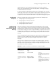
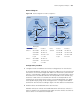
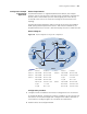
Network diagram
Figure 124 Network diagram for MSDP configuration
Configuration procedure
1 Configure interface IP addresses and unicast routing protocol on the switches.
In each PIM-SM domain, configure the interface IP addresses on the switches and
interconnect the switches through OSPF. Make sure that Switch A, Switch B and
Switch C in the PIM-SM 1 domain are interoperable on the network layer, Switch
D and Switch E in the PIM-SM 2 domain are interoperable on the network layer,
and Switch F and Switch G in the PIM-SM 3 domain are interoperable on the
network layer. On the other hand, switches in each PIM-SM domain can update
routes dynamically by using unicast routing protocols. Configure the IP address
and mask of each interface according to Figure 124. The details are omitted here.
2 Enable multicast and enable PIM-SM on each interface.
# Enable multicast on SwitchC and enable PIM-SM on all interfaces. Switch C is
taken for example. The configuration procedures on other switches are similar to
that on Switch C. The details are omitted here.
Device Interface IP address Device Interface IP address
Switch C Vlan-int100 10.110.1.1/8 Switch D Vlan-int300 10.110.4.1/8
Vlan-int200 10.110.2.1/8 Vlan-int102 192.168.3.1/24
Vlan-int101 192.168.1.1/24 Vlan-int101 192.168.1.2/24
Loop0 1.1.1.1/32 Loop0 2.2.2.2/32
Switch F Vlan-int400 10.110.3.1/8
Vlan-int102 192.168.3.2/24
Loop0 3.3.3.3/32
Vlan-int101
Vlan-int102
Switch A
Switch C
Switch B
Source 1
AS 100
PIM-SM 1
PIM-SM 3
PIM-SM 2
AS 200
Loop0
Switch D
Switch E
Switch F
Switch G
Source 2
Vlan-int200
Vlan-int
1
00
Vlan-int101
Vlan-int102
Vlan-int300
Vlan-int400
Loop0
Receiver
Receiver
Receiver
Loop0
MSDP peers