
3Com Switch 7750 Configuration Guide

MSDP Configuration Example 499
Configuration Example
of Anycast RP
Application
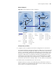
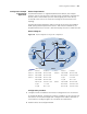
Network requirements
Each PIM-SM network is a single-BSR administrative domain, with multiple
multicast sources (S) and receivers. With Anycast RP configured in each PIM-SM
domain, when a new member joins the multicast group, the switch directly
connected to the receiver can send a Join message to the nearest RP on the
topology.
The PIM-SM network implements OSPF to provide unicast routes and establish
MSDP peering relationship between Switch C and Switch D. Meanwhile, the
Loopback10 interfaces of Switch C and Switch D play the roles of C-BSR and C-RP.
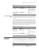
Network diagram
Figure 125 Network diagram for Anycast RP configuration
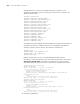
Configuration procedure
1 Configure interface IP addresses and unicast routing protocols on the switches.
In the PIM-SM domain, configure the interface IP addresses on the switches and
interconnect the switches through OSPF. Configure the IP address and mask of
each interface according to Figure 125. The details are omitted here.
2 Enable multicast and configure PIM-SM.
Device Interface IP address Device Interface IP address
Switch A Vlan-int100 10.110.1.2/24 Switch D Vlan-int100 10.110.3.1/24
Switch B Vlan-int200 10.110.2.2/24 Vlan-int101 192.168.3.2/24
Switch C Vlan-int100 10.110.1.1/24 Loop0 2.2.2.2/32
Vlan-int200 10.110.2.1/24 Loop10 10.1.1.1/32
Vlan-int110 192.168.1.1/24 Switch F Vlan-int100 10.110.4.1/24
Loop0 1.1.1.1/32 Vlan-int101 192.168.3.1/24
Loop10 10.1.1.1/32 Vlan-int110 192.168.1.2/24
Source 3
Source 2
Receiver
Receiver
Receiver
Switch A
Switch B
Switch C
Switch F
Switch D
Loop0
Loop10
Lo
o
p0
Loop10
PIM-SM
MSDP peers
Vlan-int110
Vlan-int110
V
l
an-
i
nt
2
00
V
la n
-
int2
0
0
Vlan-int100
Vlan-int100
Vlan-int101
Vlan-int101
Vlan-int100
Vlan-int100
Source 1
10.110.5.100/24