
3Com Switch 7750 Configuration Guide


502 CHAPTER 48: MSDP CONFIGURATION
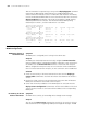
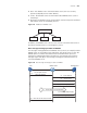
Network diagram
Figure 126 Network diagram for static RPF peer configuration
Configuration procedure
1 Configure the interface IP addresses and unicast routing protocols for each switch
Configure interface IP addresses for each switch, and configure OSPF for
interconnection between switches in each PIM-SM domain. Ensure the
network-layer interoperation among switches in PIM-SM1, the network-layer
interoperation between switches in PIM-SM2, and the network-layer
interoperation between switches in PIM-SM3, and ensure the dynamic update of
routing information between the switches in each PIM-SM domain is implemented
through a unicast routing protocol. Configure the IP address and subnet mask for
each interface as shown in Figure 126. The detailed configuration steps are
omitted.
2 Enable multicast and enable PIM-SM on each interface.
# Enable multicast on all the switches, and enable PIM-SM on each interface. The
configuration procedures on the other switches are similar to the configuration
procedure on Switch C. So the configuration procedures on the other switches are
omitted.
[SwitchC] multicast routing-enable
[SwitchC] interface vlan-interface 100
[SwitchC-Vlan-interface100] pim sm
[SwitchC-Vlan-interface100] quit
[SwitchC] interface vlan-interface 200
[SwitchC-Vlan-interface200] pim sm
[SwitchC-Vlan-interface200] quit
Static RPF peers
Source 1
Receiver
Switch A
Switch B
Switch C
PIM-SM 3
PIM-SM 2
Loop0
2.2.2.2/32
Switch F Switch E
Switch D
Switch G
Source 3
Loop0
3.3.3.3/32
Receiver
Receiver
Loop0
1.1.1.1/32
PIM-SM 1
Source 2
AS 100 AS 200
Vlan-int110
192.168 .1.1/24
Vlan-int110
192.168.1.2/24
Vl a
n
-in
t
12
0
1
9
2.
16
8
.3.
2
/24
Vlan-int120
192.1
6
8.0
.
3.1
/
24