
3Com Switch 7750 Configuration Guide


Displaying and Maintaining VRRP 559
Displaying and
Maintaining VRRP
After the above configuration, you can execute the display command in any view
to view VRRP configuration and verify the configuration effect. And in user view,
you can execute the reset command to clear the VRRP statistics and execute the
debugging command to debug the VRRP.
VRRP Configuration
Example
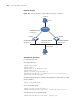
Single-VRRP Backup
Group Configuration
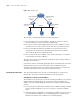
Network requirements
Host A uses the VRRP virtual router comprising switch A and switch B as its default
gateway to visit host B on the Internet.
The information about the VRRP backup group is as follows:
■ VRRP backup group ID: 1
■ Virtual router IP address: 202.38.160.111
■ Master switch: Switch A
■ Backup switch: Switch B
■ Preemptive mode: enabled
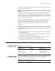
Table 436 Display and Maintain VRRP
Operation Command Description
Display the VRRP
statistics information
display vrrp statistics
[ interface interface-type
interface-number [ vrid
virtual-router-id ]]
You can execute the display
command in any view.
Display the VRRP
status information
display vrrp [ interface
interface-type interface-number
[ vrid virtual-router-id ]]
Display the detailed
VRRP information
display vrrp verbose
[ interface interface-type
interface-number [ vrid
virtual-router-id ]]
Clear the VRRP
statistics information
reset vrrp statistics [ interface
interface-type interface-number
[ vrid virtual-router-id ]]
You can execute the reset
command in user view.
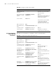
Table 437 Network description
Switch
Ethernet port
connecting to
Host A
IP address of the
VLAN interface
Switch priority in
the backup group
Preemptive
mode
LSW-A Ethernet 1/0/6 202.38.160.1/24 110 Enabled
LSW-B Ethernet 1/0/5 202.38.160.2/24 100 (default) Enabled