
3Com Switch 7750 Configuration Guide


564 CHAPTER 52: VRRP CONFIGURATION
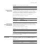
2 and a backup switch in backup group 1. Some hosts in the network take virtual
router 1 as the gateway, while others take virtual router 2 as the gateway. In this
way, both load balancing and mutual backup are implemented.
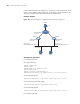
Network diagram
Figure 145 Network diagram for multiple-VRRP backup group configuration
Configuration procedure
■ Configure Switch A.
# Configure VLAN 2.
<LSW-A> system-view
[LSW-A] vlan 2
[LSW-A-vlan2] port Ethernet 1/0/6
[LSW-A-vlan2] quit
[LSW-A] interface Vlan-interface 2
[LSW-A-Vlan-interface2] ip address 202.38.160.1 255.255.255.0
# Create backup group 1.
[LSW-A-Vlan-interface2] vrrp vrid 1 virtual-ip 202.38.160.111
# Set the priority for backup group 1.
[LSW-A-Vlan-interface2] vrrp vrid 1 priority 150
# Create backup group 2.
[LSW-A-Vlan-interface2] vrrp vrid 2 virtual-ip 202.38.160.112
■ Configure Switch B.
Switch A
Host C
Host B
Switch B
VLAN-Interface3:
10.100 .10.2
VLAN-Interface2:
202.38.160 .1
VLAN-Interface2:
202.38.160 .2
202.38.160.3
10.2.3.1
Host A
202.38.160 .4
Internet
Backup group 1:
Virtual IP address
202.38.160.111
Backup group 2 :
Virtual IP address 2
02.38.160 .112