
3Com Switch 7750 Configuration Guide


ARP Configuration Example 581
ARP Packet Rate Limit
Configuration Example
Network requirements
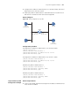
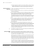
As shown in Figure 147, Ethernet 2/0/1 of Switch A connects to DHCP Server;
Ethernet 2/0/2 connects to Client A, Ethernet 2/0/3 connects to Client B. Ethernet
2/0/1, Ethernet 2/0/2 and Ethernet 2/0/3 belong to VLAN 1.
■ Enable DHCP snooping on Switch A and specify Ethernet 2/0/1 as the trusted
port for DHCP snooping and ARP packet rate limit.
■ Enable the ARP packet rate limit function, so as to prevent Client A and Client
B from attacking Switch A through ARP traffic.
■ Enable the port state auto recovery function on the ports of Switch A, and set
the recovery interval to 200 seconds.
Network diagram
Figure 147 ARP packet rate limit configuration
Configuration procedure
# Enable DHCP snooping on Switch A.
<SwitchA> system-view
[SwitchA] dhcp-snooping
# Specify Ethernet 2/0/1 as the trusted port for DHCP snooping and ARP packet
rate limit.
[SwitchA] interface Ethernet2/0/1
[SwitchA-Ethernet2/0/1] dhcp-snooping trust
[SwitchA-Ethernet2/0/1] arp detection trust
[SwitchA-Ethernet2/0/1] quit
# Enable the ARP packet rate limit function, and set the maximum ARP packet rate
allowed on the port to 20 pps.
[SwitchA] arp rate-limit enable
[SwitchA] arp rate-limit 20
# Configure the port state auto recovery function, and set the recovery interval to
200 seconds.
Eth2/0/3
Client B
Eth2/0/2
Client A
DHCP Server
Switch A
DHCP Snooping
Eth2/0/1