
3Com Switch 7750 Configuration Guide


Proxy ARP Configuration Example 585
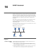
■ Configure the IP address of VLAN-interface 3 as 192.168.0.27/24, and that of
VLAN-interface 4 as 192.168.1.27/24.
■ Enable proxy ARP on VLAN-interface 3 and VLAN-interface 4 to allow Host A
and Host D to communicate with each other through ARP.
Network diagram
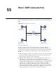
Figure 149 Network diagram for proxy ARP
Configuration procedure
# Configure the IP address of VLAN-interface 3 as 192.168.0.27/24.
<Switch> system-view
[Switch] interface Vlan-interface 3
[Switch-Vlan-interface3] ip address 192.168.0.27 24
[Switch-Vlan-interface3] quit
# Configure the IP address of VLAN-interface 4 as 192.168.1.27/24
[Switch] interface Vlan-interface 4
[Switch-Vlan-interface4] ip address 192.168.1.27 24
[Switch-Vlan-interface4] quit
# Enable proxy ARP on VLAN-interface 3.
[Switch] interface Vlan-interface 3
[Switch-Vlan-interface3] arp proxy enable
[Switch-Vlan-interface3] quit
# Enable proxy ARP on VLAN-interface 4.
[Switch] interface Vlan-interface 4
[Switch-Vlan-interface4] arp proxy enable
[Switch-Vlan-interface4] quit
Super VLAN Proxy ARP
Configuration Example
Network requirements
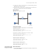
■ Create a super VLAN, VLAN 10 and configure the IP address of VLAN-interface
10 as 192.168.10.100/16.
192.168.0.22/16
Host A Host B
Host C
Host D
192.168.1.30/16
Vlan-int3
192.168.0.27/24
Vlan-int4
192.168.1.27/24
Switch